
Backfill area foundation pit supporting structure and construction method thereof

A foundation pit support and construction method technology, applied in the direction of foundation structure engineering, excavation, sheet pile walls, etc., can solve the problems of long time consumption, increased construction cost, and difficult drilling, so as to increase anti-overturning ability and save Construction cost, effect of reducing construction cost

Inactive Publication Date: 2020-08-21
北京市地质工程有限责任公司
View PDF6 Cites 7 Cited by
  • Summary
  • Abstract
  • Description
  • Claims
  • Application Information

AI Technical Summary

Problems solved by technology

[0005] The above-mentioned existing technical solutions have the following defects: when the foundation pit of the building is in the backfill area of ​​the sand mining pit, since the geology of the sand mining pit is formed by backfilling construction waste and domestic waste, the compactness of the sand pit itself is low and cannot be used as an anchor. The poles and slope protection piles provide sufficient resistance to pullout and overturning. If the stability of the anchor rods and slope protection piles is to be increased, the length of the anchor rods and slope protection piles needs to be lengthened to increase the force of the surrounding soil on the anchor rods and slope protection piles. So as to ensure the stability of both, but this method is more and more difficult to drill because the formation is getting harder and harder, and it takes a long time to drill in place, which greatly increases the construction cost

Method used


Image

  • Backfill area foundation pit supporting structure and construction method thereof
  • Backfill area foundation pit supporting structure and construction method thereof

Examples


Embodiment Construction

[0037] The present invention will be described in further detail below in conjunction with the accompanying drawings.

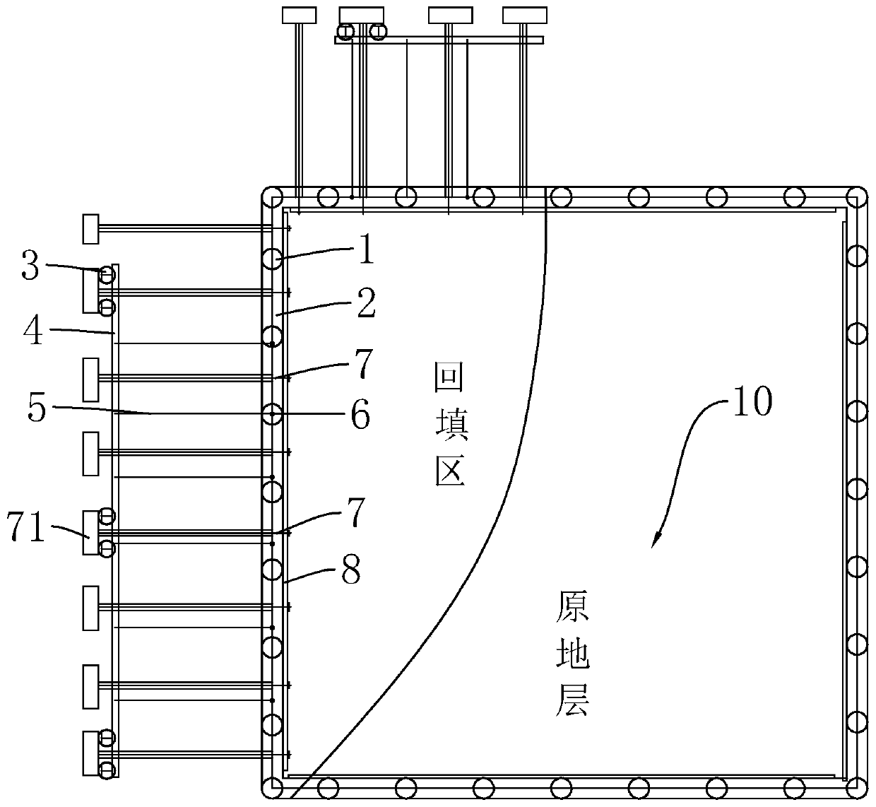
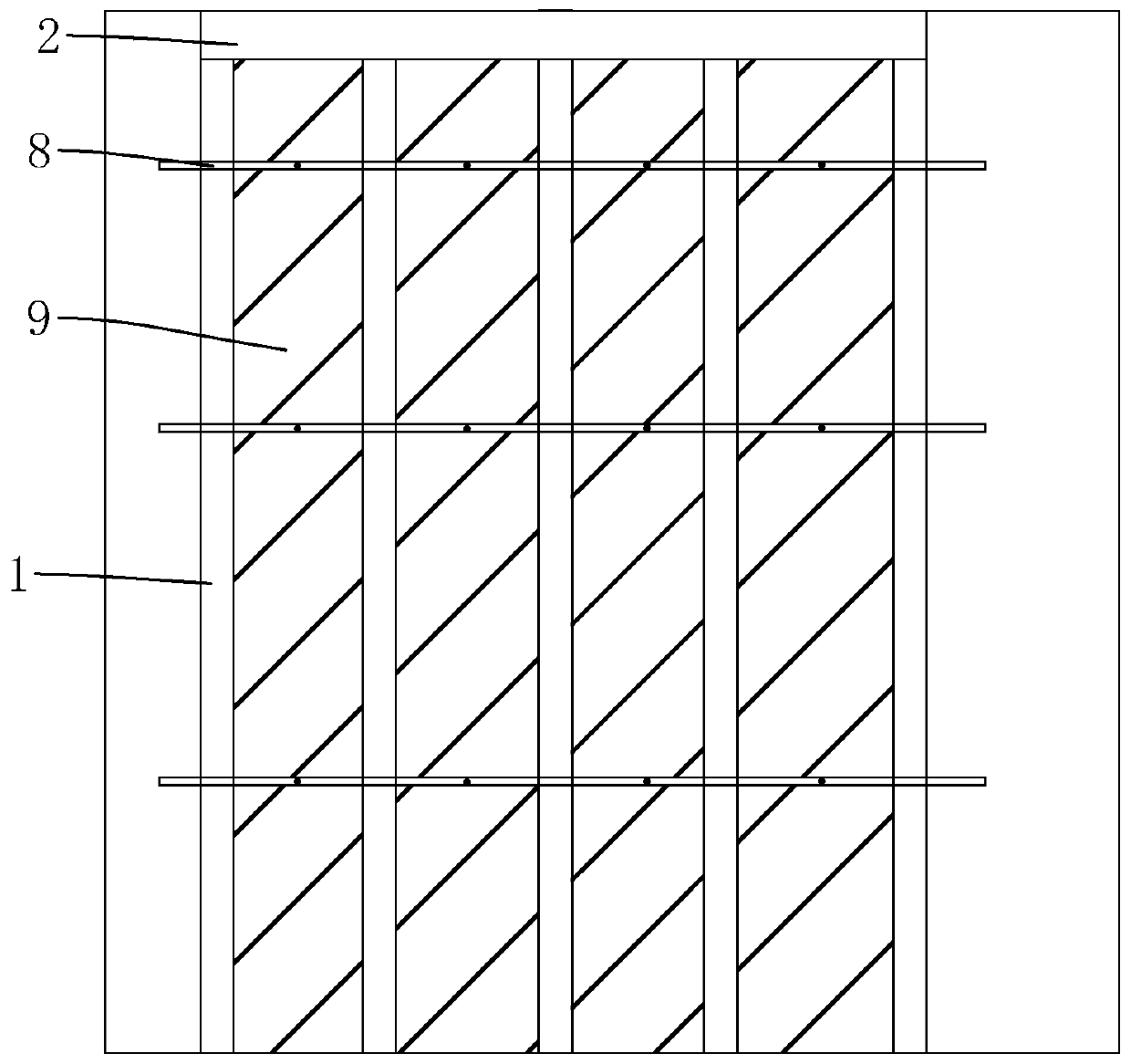
[0038] refer to figure 1 and figure 2 , is a construction method of foundation pit support structure in backfill area disclosed by the present invention, taking the actual construction case foundation pit depth of 14-15m, slope protection pile 1 length of 18-20m as an example. It should be noted that the foundation pit at the normal stratum adopts the normal pile-anchor support method, and the foundation pit at the backfill area adopts the following support method, and the construction steps are as follows:

[0039] S1. Construct the slope protection pile 1 and the crown beam 2 along the surroundings of the foundation pit 10 to be excavated. The specific construction steps are as follows: lay out the line according to the design position and mark the center position of the slope protection pile 1, and the center distance between adjacent slope protection pi...


PUM


Abstract

The invention relates to a construction method of a backfill area foundation pit supporting structure. The construction method comprises the following steps: S1, constructing slope protection piles and top beams; S2, constructing a plurality of pairs of profile steel cement soil mixing piles on the sides, away from a foundation pit to be excavated, of the slope protection piles, wherein each pairof profile steel cement soil mixing piles are arranged at intervals, the multiple pairs of profile steel cement soil mixing piles are connected into a whole through cross beams, and the cross beams are connected with the top beams of the supporting piles in a pulled mode; S3, excavating the foundation pit in a layered mode, and then carrying out anchor rod construction on the side wall of the foundation pit, wherein the tail ends of the anchor rods penetrate through the space between each pair of profile steel cement soil mixing piles, grouting is carried out in anchor rod holes, sectional grouting is adopted, and expanded heads are formed at the ends, extending out of the profile steel cement soil mixing piles, of the anchor rods; and S4, carrying out waist beam construction, and carryingout excavation of a foundation pit of the next layer. The profile steel cement soil mixing piles are arranged behind the slope protection piles, the pulling and fixing effects on the slope protectionpiles are achieved, meanwhile, anchor rod grouting bodies are matched with the profile steel cement soil mixing piles to increase the pulling resistance of the anchor rods, and therefore the stability of pile-anchor supporting is improved.

Description

technical field [0001] The invention relates to the technical field of foundation pit support, in particular to a foundation pit support structure in a backfill area and a construction method thereof. Background technique [0002] The foundation pit support is to ensure the safety of the underground structure construction and the surrounding environment of the foundation pit, and the support, reinforcement and protection measures adopted for the side wall of the foundation pit and the surrounding environment. [0003] In recent years, many sand mining pits formed due to sand mining activities have accumulated a lot of construction waste and domestic waste in the later stage, and the original sand mining pits are all filled by construction waste and domestic waste. However, with the acceleration of the urban construction process, land resources are becoming increasingly scarce, many areas are built as buildings, the scale of the buildings is getting larger and larger, and the...

Claims


Application Information

Patent Timeline
Patent Type & Authority Applications(China)
IPC IPC(8): E02D17/04E02D5/76
CPCE02D5/765E02D17/04E02D2250/0023E02D2250/0046
Inventor 沈元红
Owner 北京市地质工程有限责任公司
Learn More