
Driving mechanism and lens anti-shake device

A driving mechanism and lens technology, applied in projection devices, printing devices, cameras, etc., can solve the problems of complex micro voice coil motor structure, small optical anti-shake stroke, and reduce the effect of anti-shake, so as to achieve light product structure, The effect of small size and miniaturized product structure

Pending Publication Date: 2020-08-18
SEADEC TECH LTD
View PDF0 Cites 5 Cited by
  • Summary
  • Abstract
  • Description
  • Claims
  • Application Information

AI Technical Summary

Problems solved by technology

A common optical image stabilization actuator is a miniature voice coil motor, which generates a Loren magnetic force in a magnetic field through an energized coil to drive the lens to move; and to achieve optical image stabilization, the lens needs to be driven in at least two directions, which It means that multiple coils need to be arranged, which will bring certain challenges to the miniaturization of the overall structure; and the micro voice coil motor is not only complex in structure and large in size, but also realizes a small optical anti-shake stroke, which is difficult to meet the demand and reduces the anti-shake The effect of shaking

Method used


Image

  • Driving mechanism and lens anti-shake device
  • Driving mechanism and lens anti-shake device
  • Driving mechanism and lens anti-shake device

Examples


Embodiment Construction

[0024] The idea, specific structure and technical effects of the present invention will be further described below in conjunction with the accompanying drawings, so as to fully understand the purpose, features and effects of the present invention.

[0025] It should be noted that, in the description of the present invention, terms such as "up", "down", "left", "right", "vertical", "horizontal", "inside", "outside" and so on indicate directions or The terms of positional relationship are based on the direction or positional relationship shown in the drawings, which are only for convenience of description, and do not indicate or imply that the device or element must have a specific orientation, be constructed and operated in a specific orientation, and therefore cannot be understood To limit the present invention.

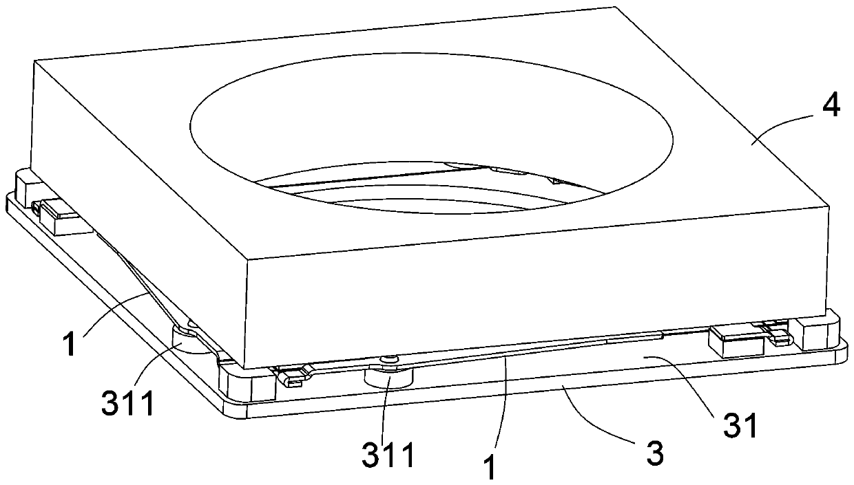
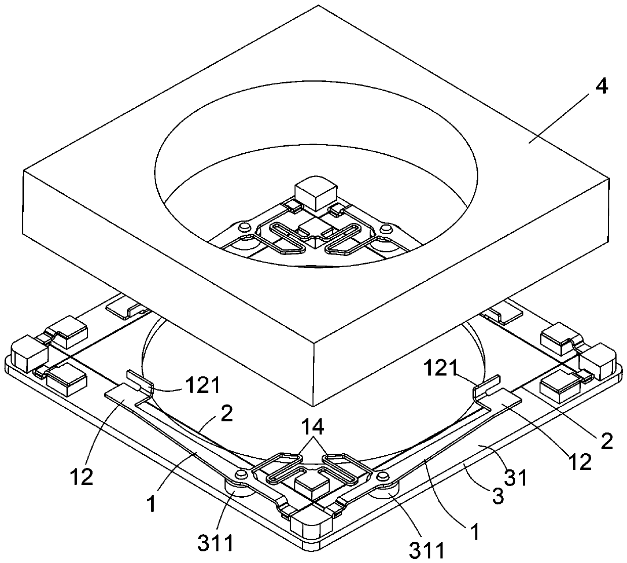
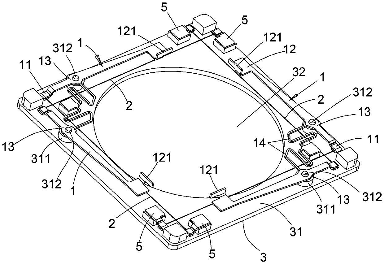
[0026] refer to figure 2 , 3 , 4 is a schematic diagram of a driving mechanism proposed by the present invention, which has a driving rod 1 and an SMA wire 2, the...


PUM


Abstract

The invention relates to a driving mechanism and a lens anti-shake device, the driving mechanism is provided with a driving rod and an SMA wire, the driving rod is provided with a power input end, a power output end and a transfer part, and the distance from the power input end to the transfer part is smaller than the distance from the power output end to the transfer part; the transfer part provides a fulcrum for synchronous rotation of the power input end and the power output end; one end of the SMA wire is connected with the power input end of the driving rod, the other end of the SMA wireis fixedly arranged, and the SMA wire provides actuating force to drive the power input end of the driving rod to rotate, so that the power output end synchronously follows rotation and enlarges the rotation arc length. In the lens anti-shake device, the power output end acts on the lens carrier, so that the lens carrier rotates around the optical axis of the lens, the optical anti-shake functionis realized, and the use performance of the lens is improved. The driving mechanism is small in size, the driving structure is simplified, the requirement for product miniaturization is met, large-stroke anti-shaking is achieved through the lever principle, control is easy, convenient and accurate, and the driving mechanism is suitable for application and popularization.

Description

technical field [0001] The invention relates to the technical field of drive mechanisms, in particular to a drive mechanism for lens anti-shake. Background technique [0002] With the advancement of science and technology, the application of camera modules is becoming more and more extensive. At present, in addition to cameras, electronic devices such as mobile phones and computers are equipped with camera modules to facilitate people to take pictures anytime and anywhere, bringing convenience to people's lives. with fun. The camera module includes a fixed-focus (FF) camera module and an auto-focus (AF) camera module. In the auto-focus (AF) camera module, the lens can be driven by a lens driving device (motor) to achieve focusing. When taking pictures or videos, the lens will not be able to keep absolutely stable due to human shaking or other reasons, resulting in a certain offset. At this time, the focus and light input of the camera will be affected, which will affect the...

Claims


Application Information

Patent Timeline
IPC IPC(8): G02B27/64G03B5/00
CPCG02B27/646G03B5/00
Inventor 刘述伦耿新龙计树标
Owner SEADEC TECH LTD
Learn More