Quick limiting locking structure

A locking structure and position-limiting technology, applied in the field of firearms, can solve the problems of cumbersome decomposition and combination, poor ergonomics, etc., and achieve the effects of good ergonomics, convenient operation and novel structure

Pending Publication Date: 2020-08-18
CHONGQING JIANSHE IND GRP
View PDF0 Cites 2 Cited by
  • Summary
  • Abstract
  • Description
  • Claims
  • Application Information

AI Technical Summary

Problems solved by technology

[0002] In the structural design of modern firearms, it is often encountered that both limit and locking are required, such as the connection of firearm accessories such as handguards and quasi-constellations with barrel parts. The traditional solution is generally to use screw locking to limit the position. position, the decomposition and combination are cumbersome, and the man-machine efficiency is poor

Method used


Image

  • Quick limiting locking structure
  • Quick limiting locking structure
  • Quick limiting locking structure

Examples


Embodiment Construction

[0032] The working principle and structure of the present invention will be further described in detail below in conjunction with the embodiments and the accompanying drawings.

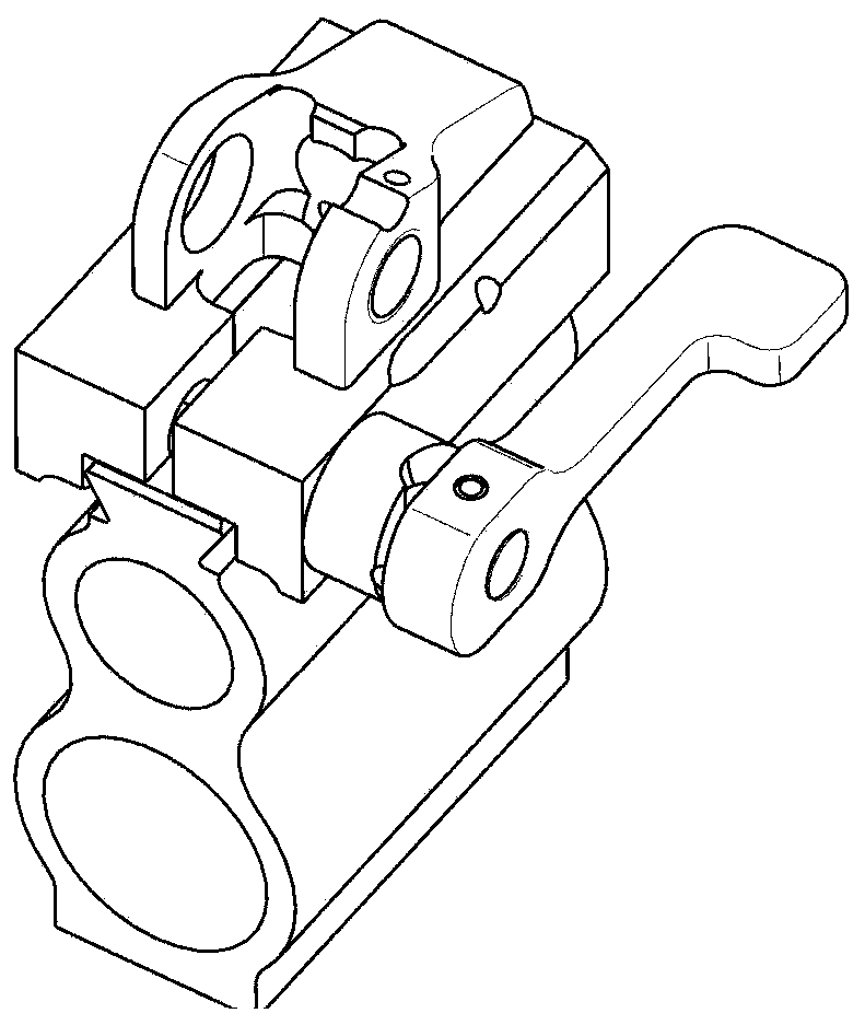
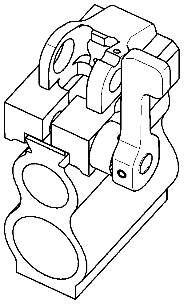
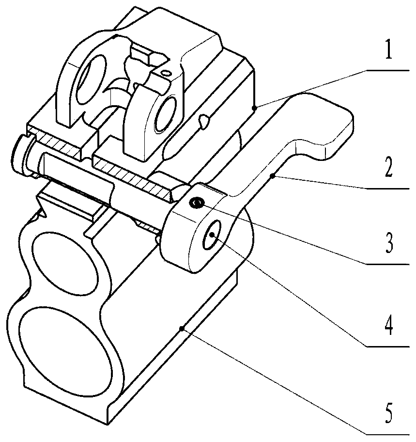
[0033] Such as Figure 1 to Figure 9 Shown, a kind of quick limit locking structure comprises base 5, dovetail seat 1, limit shaft 4 and handle 2, and gun barrel part (not shown) is installed on the base 5, the upper part of base 5 A dovetail interface 502 is provided along the axial direction of the barrel part, and a notch 501 is provided along the radial direction of the barrel part; firearm accessories are installed on the dovetail seat 1, which is arranged above the base 5, and the bottom of the dovetail seat 1 is opened along the axial direction of the barrel part There is a dovetail groove 105, the base 5 and the dovetail seat 1 are slidingly connected through the dovetail interface 502 and the dovetail groove 105, and the tail of the dovetail seat 1 is provided with a longitudinal groove 101, ...


PUM


Abstract

The invention discloses a quick limiting locking structure. The quick limiting locking structure comprises a base, a dovetail seat, a limiting shaft and a handle, a groove opening is formed in the upper part of the base, the dovetail seat is arranged above the base and slidably connected with the base, the tail of the dovetail seat is provided with a longitudinal groove, one side of the tail of the dovetail seat is provided with a cylindrical part, the end face of the cylindrical part is provided with a spiral face, a limiting shaft is arranged at the tail of the dovetail seat in a sleeving mode, one end of the limiting shaft is in threaded connection with a handle, one side of the limiting shaft is provided with a notch, a boss is arranged on one side of the handle, the boss is matched with the spiral face of the dovetail seat, a lock pin is arranged on the handle in the radial direction and used for stopping rotation when the handle and the limiting shaft are connected, in a naturalstate, the handle is in a vertical state, the boss of the handle is located at the lowest position of the spiral face, the cylindrical face of the limiting shaft is separated from the groove opening of the base, the dovetail seat can be slidably separated from the base, when limiting locking is needed, the handle is rotated, the boss of the handle climbs from the low position of the spiral face tothe high position of the spiral face to lock the dovetail seat and the base, after the handle is rotated by 90 degrees, the boss of the handle is separated from the spiral face, and at the moment, the cylindrical face of the limiting shaft is superimposed with the groove opening of the base to limit sliding of the dovetail seat and the base.

Description

technical field [0001] The invention relates to the technical field of firearms, in particular to a fast position-limiting locking structure. Background technique [0002] In the structural design of modern firearms, it is often encountered that both limit and locking are required, such as the connection of firearm accessories such as handguards and quasi-constellations with barrel parts. The traditional solution is generally to use screw locking to limit the position. Position, disassembly and combination are cumbersome, and the man-machine efficiency is poor. Contents of the invention [0003] The purpose of the present invention is to solve the problems existing in the prior art, to provide a fast limit locking structure, which can quickly realize the installation of firearm accessories and firearms, is easy to operate, can be quickly decomposed and combined and locked and limited, and has better human-machine function. [0004] In order to achieve the above object, t...

Claims


Application Information

Patent Timeline
Patent Type & Authority Applications(China)
IPC IPC(8): F41G1/02F41G1/16F41C23/16
CPCF41C23/16F41G1/02F41G1/16
Inventor 朱开钰黄光富王冲刘科言张言罗波蔡崧宋维东黄俊叶云凯张渝龙建华李小平陈胜雷敬
Owner CHONGQING JIANSHE IND GRP
Why Eureka
Try Eureka