
Damping method and damping device based on tension-torsion coupling effect

A technology of coupling effect and shock absorption device, applied in the field of mechanical shock absorption, can solve the problems of difficult maintenance, poor shock absorption effect, and difficult maintenance of hydraulic buffer.

Active Publication Date: 2021-04-06
SUN YAT SEN UNIV
View PDF0 Cites 0 Cited by
  • Summary
  • Abstract
  • Description
  • Claims
  • Application Information

AI Technical Summary

Problems solved by technology

[0003] In the prior art, in order to adapt to different shock absorption methods and different impact directions, the structure of the shock absorber is often different. For example, in the shock absorption scheme of the bridge, the most common shock absorption method is the Corresponding shock-absorbing components are set at the seat position for shock-absorbing, and the shock-absorbing components often achieve the purpose of shock-absorbing only by storing and releasing elastic potential energy. Although this shock-absorbing method can also achieve the effect of shock-absorbing , but it will release a secondary impact during shock absorption, which will cause the shock absorber to cause secondary damage to the shock absorption object during the shock absorption process, which will lead to poor shock absorption effect, so most of the current shock absorption The purpose of the device is to avoid the impact of the above problems on the shock-absorbing object
The use of hydraulic devices for buffering is an effective solution, but the combination of hydraulic buffers can achieve buffering effects, and because hydraulic buffers are difficult to maintain, when subjected to continuous and strong impacts, the durability of traditional hydraulic buffers Tried and tested, shock absorbers are susceptible to damage and not easy to repair

Method used


Image

  • Damping method and damping device based on tension-torsion coupling effect
  • Damping method and damping device based on tension-torsion coupling effect
  • Damping method and damping device based on tension-torsion coupling effect

Examples


Embodiment 1

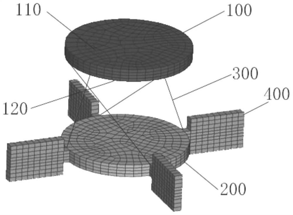
[0058] Such as figure 1 and Figure 4 As shown, this embodiment discloses a damping method based on the tension-torsion coupling effect, and the method includes

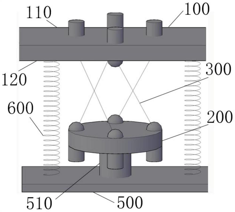
[0059] When the upper side 110 of the first end plate 100 is impacted, the first end plate 100 is moved toward the turntable 200 to shorten the distance between the first end plate 100 and the turntable 200;

[0060] When the distance between the first end plate 100 and the turntable 200 is shortened, the first end plate 100 drives the turntable 200 to rotate through the transmission of the transmission rod 300, and at the same time the elastic member 600 is compressed;

[0061] The damping fluid passing through the filling chamber prevents the rotation of the turntable 200;

[0062] After the impact is over, the elastic potential energy stored in the elastic mechanism 600 is released to restore the first end plate 100 and the turntable 200 to their original positions, and at the same time, the damping fluid fillin...

Embodiment 2

[0071] Such as figure 1 and image 3 As shown, this embodiment discloses a shock absorbing device based on the tension-torsion coupling effect, which is used to perform work on the damping fluid through viscous resistance when the bridge is subjected to an external impact, so as to convert the impact potential energy into the kinetic energy of the turntable and then into The internal energy of the damping fluid liquid, including

[0072] The filling chamber, the first end plate 100, the turntable 200, the elastic member 600 and at least two transmission rods 300;

[0073] The filling chamber is filled with damping fluid, and the damping fluid is used to limit the rotation of the turntable 200;

[0074] The first end plate 100 includes an upper side 110 and a lower side 120, the upper side 110 is a force-bearing surface, the lower side 120 faces the turntable 200, and the first end plate 100 can only move toward the direction of the turntable 200;

[0075] The turntable 200 ...

Embodiment 3

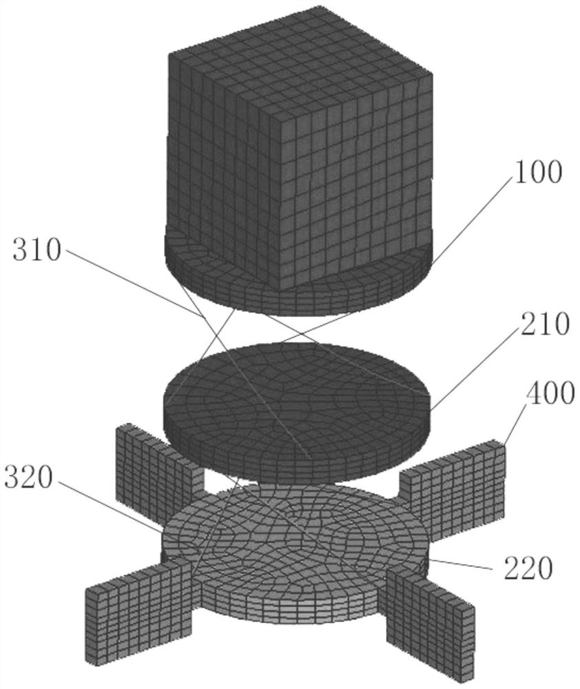
[0094] Such as figure 1 and figure 2 As shown, this embodiment discloses a shock absorber based on the tension-torsion coupling effect, including

[0095] At least one further turntable 200 is included;

[0096] The lower surface of the turntable 200 faces the upper surface of another turntable 200, and the other turntable 200 is arranged in the filling chamber;

[0097] The number of the transmission rods 300 is at least 4, and at least 2 transmission rods 300 are placed obliquely between the turntable 200 and another turntable 200, and one end of the transmission rod 300 is rotationally connected with the lower surface of the turntable 200, and the other end is connected with the lower surface of the turntable 200. The upper surface of the other turntable 200 is rotatably connected.

[0098] In the case of higher buffer requirements, the shock absorbing device also includes another turntable 200, the other turntable 200 is under the original turntable 200, and the connec...


PUM


Abstract

The invention provides a shock absorbing method and a shock absorbing device based on the tension-torsion coupling effect. The invention relates to the field of mechanical shock absorbing, wherein the method includes: when the upper side of the first end plate is impacted, using The first end plate moves toward the direction of the turntable to shorten the distance between the first end plate and the turntable; when the distance between the first end plate and the turntable is shortened, the first end plate drives the turntable through the transmission of the transmission rod The rotation of the elastic member is performed while the elastic member is compressed; the damping fluid passing through the filling chamber prevents the rotation of the turntable; after the impact is over, the elastic potential energy stored in the elastic mechanism is released to restore the first end plate and the turntable to their original positions, and at the same time The damping fluid passing through the filling chamber prevents the rotation of the turntable. The problem of how to avoid the secondary damage caused by the elastic member to the shock-absorbing object during the shock-absorbing process is solved.

Description

technical field [0001] The present invention relates to the field of mechanical damping, and more specifically, to a damping method and a damping device based on tension-torsion coupling effect. Background technique [0002] Shock absorber is a kind of mechanical equipment commonly used to absorb external shocks. The earliest shock absorber just refers to the spring with a high elastic coefficient arranged between components. In order to be able to adapt to different scenarios, it has undergone many researches. And after practice, the current shock absorbers have a variety of shock absorption methods. [0003] In the prior art, in order to adapt to different shock absorption methods and different impact directions, the structure of the shock absorber is often different. For example, in the shock absorption scheme of the bridge, the most common shock absorption method is the Corresponding shock-absorbing components are set at the seat position for shock-absorbing, and the sh...

Claims


Application Information

Patent Timeline
Patent Type & Authority Patents(China)
IPC IPC(8): E01D19/00
CPCE01D19/00
Inventor 胡玲玲叶文康殷秋运
Owner SUN YAT SEN UNIV
Learn More