Vertical vibration reduction support
A vertical and upper seat technology, applied in the direction of spring/shock absorber, vibration suppression adjustment, non-rotational vibration suppression, etc., can solve the problem that the vertical bearing capacity and vibration reduction function cannot be provided at the same time, the vertical height of the device is large, and the structure is complex. and other problems, to achieve the effect of simple and reliable device structure, convenient construction and installation, and clear force
- Summary
- Abstract
- Description
- Claims
- Application Information
AI Technical Summary
Problems solved by technology
Method used
Image
Examples
Embodiment 1
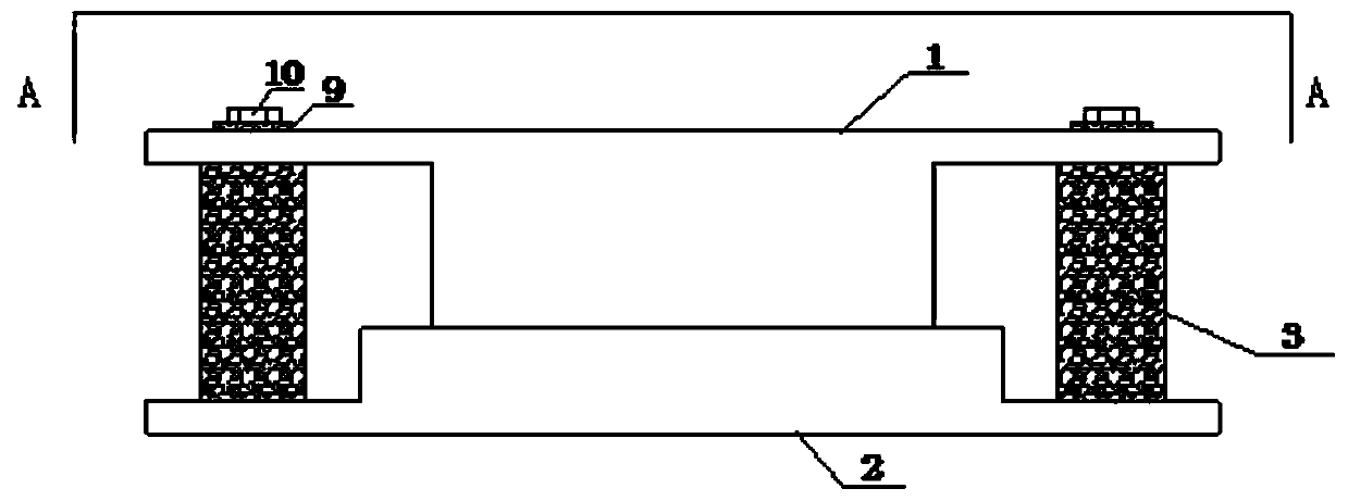
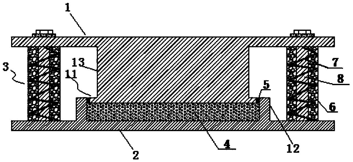
[0033] Such as Figure 1~2 As shown, a vertical damping support includes an upper seat plate 1 and a lower seat plate 2 . Between the upper seat plate 1 and the lower seat plate 2 are provided a bearing portion 11 capable of reducing vibration and energy consumption, and a damping system 3 for reducing vibration and energy consumption.
[0034] The bearing part 11 includes a raised flange 12 arranged on the lower seat plate 1, a hollow accommodation cavity formed by the flange 12 and the lower seat plate 2, an elastic pad 4 arranged in the accommodation cavity, and an upper seat plate 1 fixedly connected support part 13. The elastic pad 4 is a high damping rubber pad or other elastic body material. The support portion 13 is integrally formed with the upper seat plate 1 .
[0035] The top of the accommodating cavity is open. The supporting part 13 is inserted into the accommodating cavity, and the supporting part 13 is in contact with the top of the elastic pad 4 .
[0036...
Embodiment 2
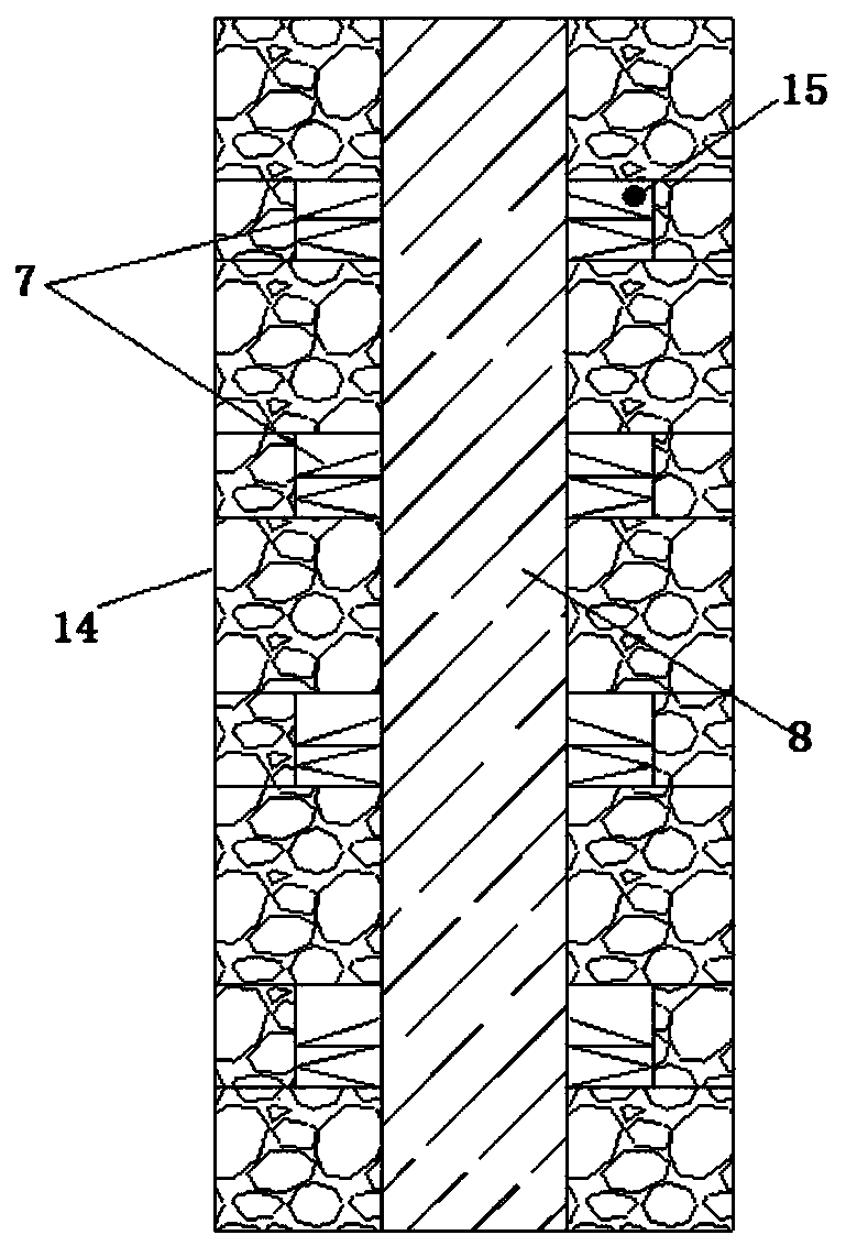
[0043] Repeat Example 1, except that, as image 3 As shown, the damping system 3 has different structures. The rubber spring damping system of this embodiment includes a guide rod 8 arranged between the upper seat plate 1 and the lower seat plate 2 , and a hollow high-damping rubber sleeve 14 sleeved on the guide rod 8 .
[0044] An installation groove 15 for installing the spring 7 is spaced apart on the inner wall of the high damping rubber sleeve 14 . A spring 7 is arranged in the mounting groove 15 . The guide rod 8 passes along the central axis of the spring 7 .
[0045] The outer surface of the high damping rubber sleeve 14 is provided with a neoprene protective layer.
PUM
 Abstract
Description
Claims
Application Information
 - R&D
- Intellectual Property
- Life Sciences
- Materials
- Tech Scout
- Unparalleled Data Quality
- Higher Quality Content
- 60% Fewer Hallucinations
Browse by: Latest US Patents, China's latest patents, Technical Efficacy Thesaurus, Application Domain, Technology Topic, Popular Technical Reports.
© 2025 PatSnap. All rights reserved.Legal|Privacy policy|Modern Slavery Act Transparency Statement|Sitemap|About US| Contact US: help@patsnap.com


