A Milling Machine Fixture for Chip Removal

A milling machine fixture, a convenient technology, applied in the direction of clamping, manufacturing tools, metal processing machinery parts, etc., can solve the problems of waste of resources, low interchangeability, and difficult cleaning

Active Publication Date: 2020-11-13
无锡锡西模锻有限公司
View PDF8 Cites 0 Cited by
  • Summary
  • Abstract
  • Description
  • Claims
  • Application Information

AI Technical Summary

Problems solved by technology

[0002] The processing of special-shaped workpieces requires customized supporting fixtures to ensure their processing accuracy, and the interchangeability of special-shaped workpieces is extremely low, and the corresponding fixtures are basically disposable products. Too many customized fixtures not only increase the cost in the production process, but also It is a waste of resources. After the processing is completed, the waste on the fixture is usually cleaned manually. Without special tools and protective gear, it is difficult to clean

Method used


Image

  • A Milling Machine Fixture for Chip Removal
  • A Milling Machine Fixture for Chip Removal
  • A Milling Machine Fixture for Chip Removal

Examples


Embodiment Construction

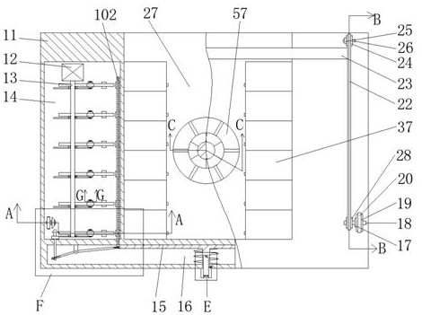
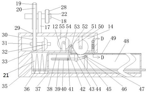
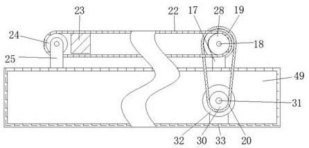
[0021] Combine below Figure 1-Figure 8 The present invention is described in detail, and for convenience of description, the orientations mentioned below are now stipulated as follows: figure 1 The up, down, left, right, front and back directions of the projection relationship itself are the same.

[0022]A milling fixture for chip removal according to the present invention includes a main body 11, the main body 11 is provided with a workpiece cavity 27 with an opening forward, and the center of the rear wall of the workpiece cavity 27 is connected with a shaft cavity with a forward opening 57, a push plate 59 is provided for sliding back and forth in the shaft cavity 57, and a variable shaft power cavity 65 is provided on the rear side of the push plate 59, and a guide rail 58 is fixedly connected to the front end of the push plate 59, and the front side of the guide rail 58 Slidingly connected with a variable shaft 64, the variable shaft 64 is provided with a pull block gu...


PUM


Abstract

The present invention discloses a milling machine clamp that is convenient for chip removal, comprising a main body, the main body is provided with a workpiece cavity with an opening forward, and the center of the rear wall of the workpiece cavity is connected with a shaft cavity with a forward opening, and the shaft cavity is A push plate is provided for sliding back and forth inside, a variable shaft power cavity is provided on the rear side of the push plate, a guide rail is fixedly connected to the front end of the push plate, and a variable shaft is slidably connected to the front side of the guide rail, and a variable shaft is provided inside the variable shaft. The block guide chamber with the opening forward; in the application of the present invention in the milling machine, the opposite movement of the left and right clamp blocks is controlled by the rotation of the transmission shaft, so as to realize the support of any special-shaped parts to be processed, and the automatic adjustment of the gear is controlled by the thimble inside the clamp block. Realize the power cut-off of the clamping block, and realize the hole positioning of different parts to be processed through the cooperation between the solid block and the variable shaft, and the change of the diameter of the variable shaft. clean up.

Description

technical field [0001] The invention relates to the field of mechanical fixtures, in particular to a milling machine fixture for chip removal. Background technique [0002] The processing of special-shaped workpieces requires customized supporting fixtures to ensure their processing accuracy, and the interchangeability of special-shaped workpieces is extremely low, and the corresponding fixtures are basically disposable products. Too many customized fixtures not only increase the cost in the production process, but also It is a waste of resources. After the processing is completed, the waste on the fixture is usually cleaned manually. Without special tools and protective gear, cleaning is difficult. [0003] A milling machine clamp that is convenient for chip removal described in the present invention can solve the above-mentioned problems. Contents of the invention [0004] In order to solve the above problems, this example designs a milling machine fixture that is conve...

Claims


Application Information

Patent Timeline
Patent Type & Authority Patents(China)
IPC IPC(8): B23Q3/06B23Q11/00
CPCB23Q3/062B23Q11/0042
Inventor 王晓强
Owner 无锡锡西模锻有限公司
Why Eureka
Try Eureka