Work machine, work machine control method, program, and recording medium for same
A technology for working machines and working tools, which is applied in the direction of earth movers/shovels, mechanically driven excavators/dredgers, construction, etc., which can solve the problems of inability to approach the stick and bucket, and the turning radius becomes larger.
- Summary
- Abstract
- Description
- Claims
- Application Information
AI Technical Summary
Problems solved by technology
Method used
Image

Examples
Embodiment approach 1
[0024] One embodiment of the present invention will be described.
[0025] (1-1. Overall structure of working machine 1)
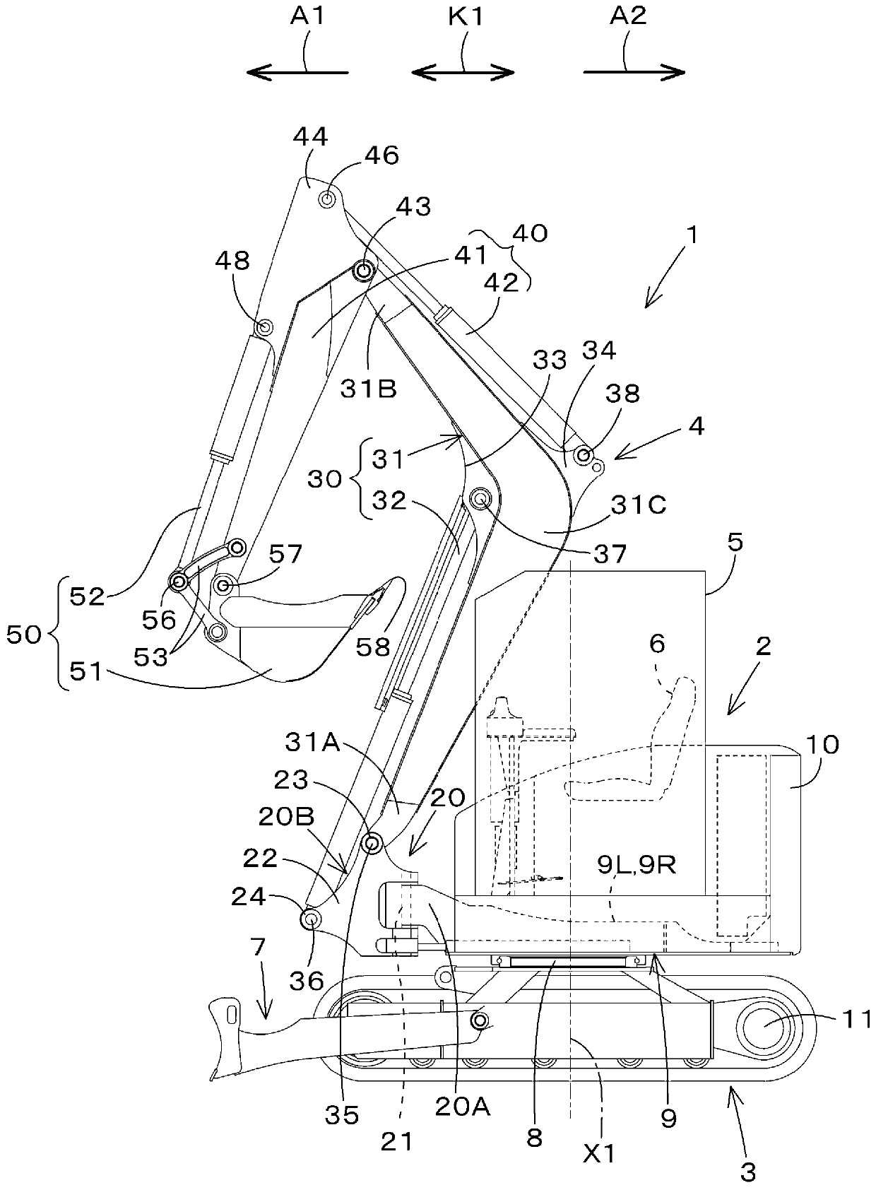
[0026] figure 1 It is a schematic side view of the work machine 1 of this embodiment. In this embodiment, a backhoe as a rotary working machine is exemplified as the working machine 1 .
[0027] Such as figure 1 As shown, the working machine 1 includes a machine body (turntable) 2 , a traveling device 3 , and a working device 4 . A cab 5 is mounted on the body 2 . A driver's seat (seat) 6 on which a driver (operator) sits is provided inside the cab 5 .
[0028] In the present embodiment, the front side ( figure 1 The direction of the arrow A1) is set to the front, and the rear side of the driver ( figure 1 The arrow A2 direction of ) is described as the rear, the driver's left side as the left side, and the driver's right side as the right side. In addition, if figure 1 As shown, the horizontal direction, which is the direction perpendicular to th...
Embodiment approach 2
[0083] Other embodiments of the present invention will be described. In addition, for convenience of description, components having the same functions as those in Embodiment 1 are given the same reference numerals, and description thereof will be omitted.
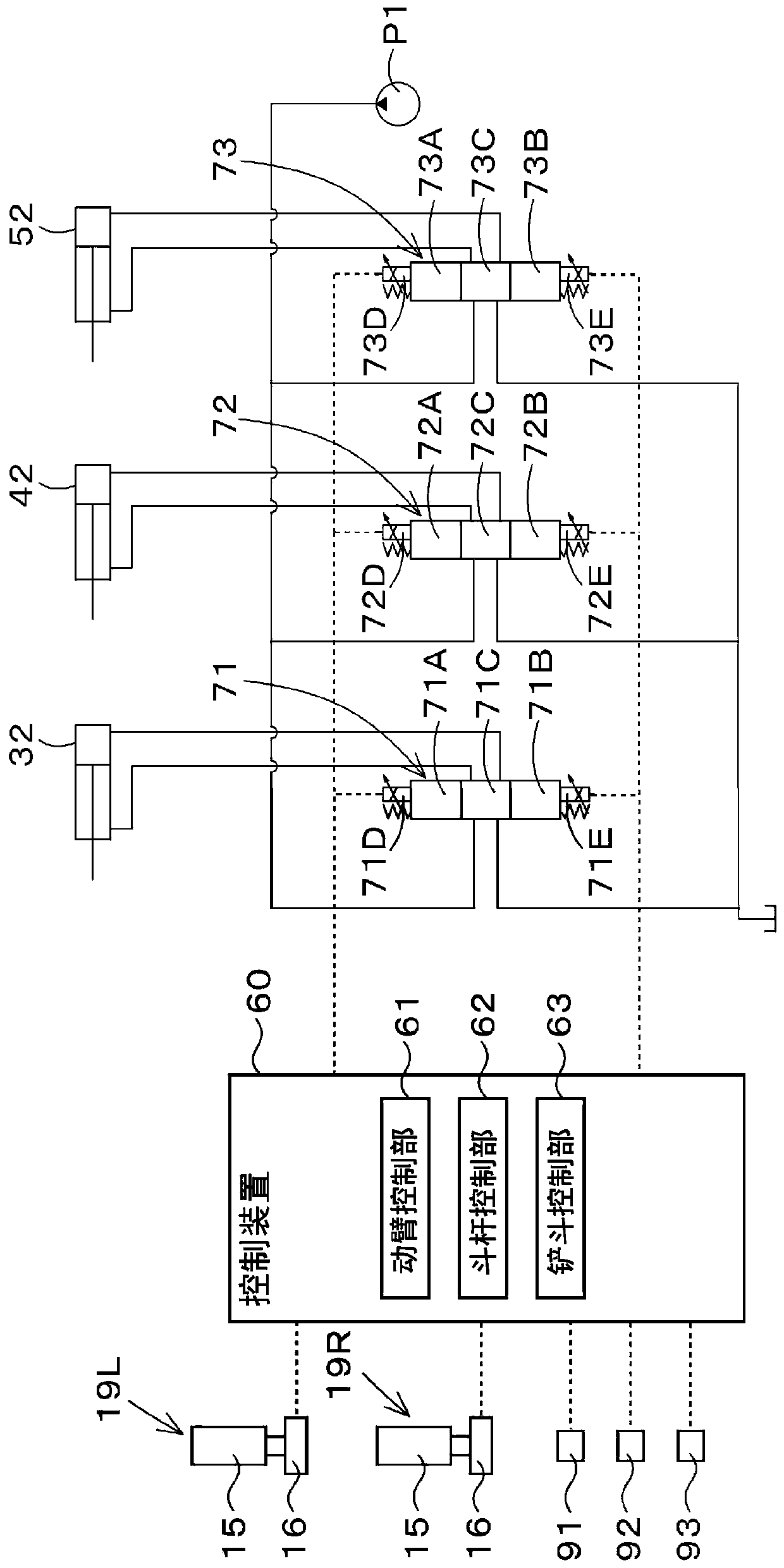
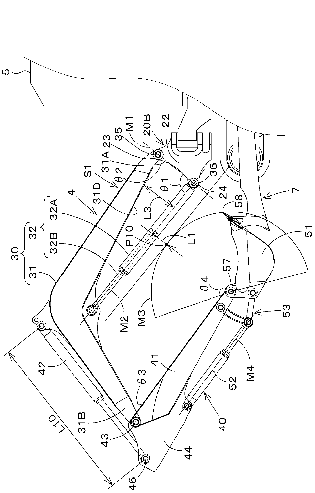
[0084] In Embodiment 1, an example in which the strokeable range of the arm cylinder 42 is set according to the rotational position of the boom 31 has been described. In contrast, in the present embodiment, the strokeable range of the arm cylinder 42 is set based on the rotational position of the boom 31 and the rotational position of the bucket 51 .
[0085] (2-1. Initial setting of the strokeable range of the arm cylinder)
[0086] First, the arm control unit 62 based on the detection result of the swing angle θ2 (rotation position) of the boom 31 by the boom angle sensor 91 , the detection result of the swing angle θ3 (rotation position) of the arm 41 by the arm angle sensor 92 and Work tool angle sensor 93 calculates ...
Embodiment approach 3
[0098] Another embodiment of the present invention will be described. It should be noted that, for convenience of description, components having the same functions as those in the above-mentioned embodiment are given the same reference numerals, and description thereof will be omitted.
[0099] In Embodiment 1, an example was described in which the strokeable range of the arm cylinder 42 is set according to the rotational position of the boom 31 regardless of the rotational position of the bucket 51 . On the other hand, in this embodiment, based on the rotational position of the boom 31 and the rotational position of the bucket 51 , it is switched whether to set the strokeable range of the arm cylinder 42 according to the rotational position of the boom 31 or whether Regardless of the rotational position of the boom 31 , the strokeable range of the arm cylinder 42 is made constant.
[0100] First, the arm control unit 62 judges that the current rotational position of the buck...
PUM
 Abstract
Description
Claims
Application Information
 - Generate Ideas
- Intellectual Property
- Life Sciences
- Materials
- Tech Scout
- Unparalleled Data Quality
- Higher Quality Content
- 60% Fewer Hallucinations
Browse by: Latest US Patents, China's latest patents, Technical Efficacy Thesaurus, Application Domain, Technology Topic, Popular Technical Reports.
© 2025 PatSnap. All rights reserved.Legal|Privacy policy|Modern Slavery Act Transparency Statement|Sitemap|About US| Contact US: help@patsnap.com