
Dimmable LED constant current source driving circuit

A driving circuit and constant current source technology, applied in the direction of electrical components, can solve the problems of insufficient energy saving and cost, and achieve the effects of reducing energy consumption, improving life, and saving electric energy

Inactive Publication Date: 2020-08-14
马少峰
View PDF5 Cites 0 Cited by
  • Summary
  • Abstract
  • Description
  • Claims
  • Application Information

AI Technical Summary

Problems solved by technology

[0005] The present invention provides a dimmable LED constant current source drive circuit, which solves the problem that the existing drive circuits all adopt a two-stage line drive with a boost-buck topology, which is not enough for energy saving and relatively high in cost

Method used


Image

  • Dimmable LED constant current source driving circuit
  • Dimmable LED constant current source driving circuit
  • Dimmable LED constant current source driving circuit

Examples


Embodiment 1

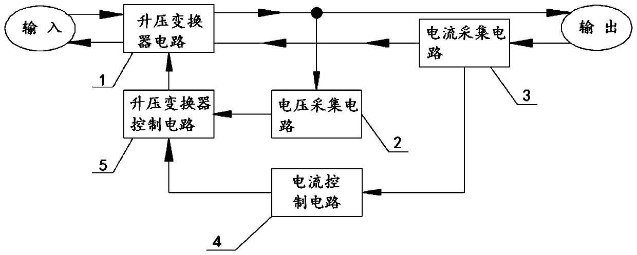
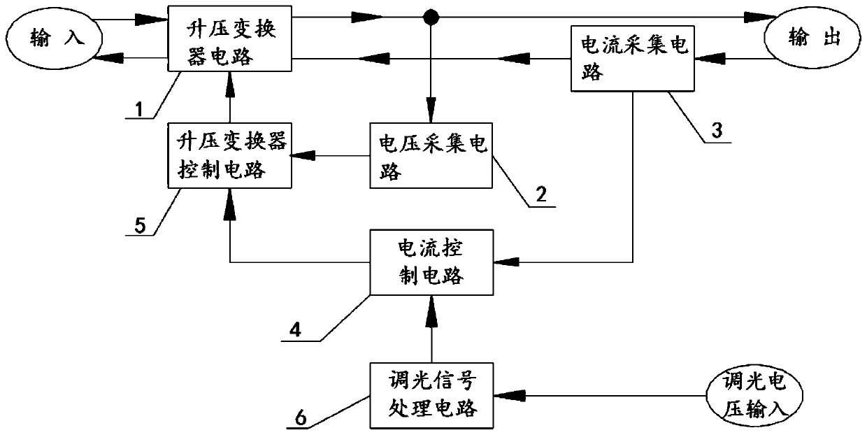
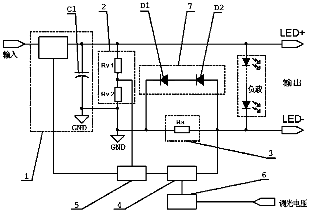
[0038] Such as figure 2As shown, this embodiment provides a dimmable LED constant current source drive circuit 1, including a boost converter circuit 1, and the output terminal of the boost converter circuit 1 is electrically connected with a voltage acquisition circuit 2 and a current Acquisition circuit 3; the voltage acquisition circuit 2 is electrically connected to a boost converter control circuit 5; the boost converter control circuit 5 is electrically connected to the boost converter circuit 1; the current acquisition circuit 3 is electrically connected to a A current control circuit 4, the current control circuit 4 is electrically connected to the boost converter control circuit 5; the current control circuit 4 is electrically connected to a dimming signal processing circuit 6; the dimming signal processing circuit 6 is used to receive The dimming voltage is converted into an input signal and transmitted to the current control circuit 4; the current acquisition circu...

Embodiment 2

[0058] On the basis of Embodiment 1, during specific implementation, the dimming signal processing circuit 6 can be omitted. At this time, the current control circuit 4 has no reference voltage D, and the reference voltage D can be changed to the reference voltage E inside the constant current control chip. . Such as figure 1 As shown, the constant current source drive without dimming function is realized; in the specific implementation, the reference current or voltage of the current control circuit is set to realize the constant current output.

[0059] The drive circuit is measured through actual calculation, and its power conversion is as high as 98%, which is very practical.


PUM


Abstract

The invention discloses a dimmable LED constant current source drive circuit which comprises a dimming signal processing circuit for receiving dimming voltage, converting the dimming voltage into an input signal and transmitting the input signal to a current control circuit; a current acquisition circuit which is used for feeding back a signal representing the real-time current of the circuit to the current control circuit; the current control circuit which receives the input signal transmitted by the dimming signal processing circuit and the signal fed back by the current acquisition circuit,and outputs a signal to a boost converter control circuit; a voltage acquisition circuit which feeds back an output voltage magnitude signal to the boost converter control circuit; the boost converter control circuit which controls a boost converter circuit to output the corresponding voltage so that the output current is constant. The dimmable constant-current source is a single-stage boosting circuit, the function loss of the dimmable constant-current source is only one stage and is much smaller than that of a traditional two-stage circuit, the heat production amount is reduced, and the service life of components is indirectly prolonged; through actual calculation and measurement, the efficiency is as high as 98%, and the practicability is high.

Description

technical field [0001] The invention belongs to the technical field of LED drive power supplies, and in particular relates to a dimmable LED constant current source drive circuit. Background technique [0002] In recent years, my country has vigorously promoted energy-saving and emission-reduction measures, and infrastructure construction is also in full swing. In the lighting industry, LED lamps are gradually becoming popular, because LED lamps are 7 to 8 times more energy efficient than traditional tungsten lamps. The index to measure whether LED lights are energy-saving is the light efficiency of LED lights. At present, the light efficiency of LED lights on the market is generally around 100lm / W, and there is still a lot of room for improvement. In order to improve the light efficiency of LEDs, one of the main ways is to improve the efficiency of LED driving power. Traditional LED drivers all adopt a boost-buck topology, which is a two-stage circuit. The front stage is ...

Claims


Application Information

Patent Timeline
Patent Type & Authority Applications(China)
IPC IPC(8): H05B45/345
CPCH05B45/345
Inventor 马少峰杨正江
Owner 马少峰
Learn More