Switching value input circuit suitable for non-polar multi-level voltage input

A digital input, voltage input technology, applied in the direction of electronic switches, circuit breaker testing, electrical components, etc., can solve problems such as inability to collect, time-consuming and labor-intensive, and damage to the collection circuit, to enhance versatility and convenience, The effect of reducing hassle and increasing efficiency

Pending Publication Date: 2020-08-14
WUHAN KEMOV ELECTRIC
View PDF0 Cites 0 Cited by
  • Summary
  • Abstract
  • Description
  • Claims
  • Application Information

AI Technical Summary

Problems solved by technology

[0003] At present, the traditional information collection method of switching value nodes relies on the conduction state of the optocoupler to judge the state of the switching value nodes. Strictly require the polarity direction of the node, otherwise, in the case of reversed polarity of the node, the acquisition will not be possible, and it is more likely to cause damage to the acquisition circuit
In addition, the node voltages of switching value acquisition in substations are also different, such as 24V, 110V and 220V, etc. Therefore, the traditional switching value acquisition circuit needs to be adjusted accordingly according to the node voltage of the switching value, and this adjustment is time-consuming. force

Method used


Image

  • Switching value input circuit suitable for non-polar multi-level voltage input
  • Switching value input circuit suitable for non-polar multi-level voltage input
  • Switching value input circuit suitable for non-polar multi-level voltage input

Examples


Embodiment Construction

[0028] In order to facilitate those of ordinary skill in the art to understand and implement the present invention, the present invention will be further described in detail below in conjunction with embodiments. It should be understood that the embodiments described here are only used to illustrate and explain the present invention, and are not intended to limit the present invention.

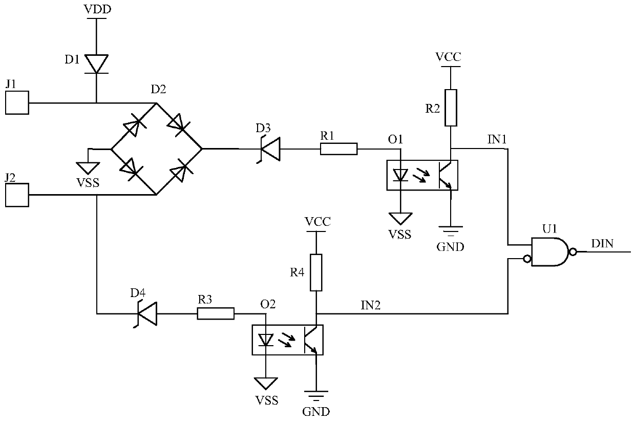
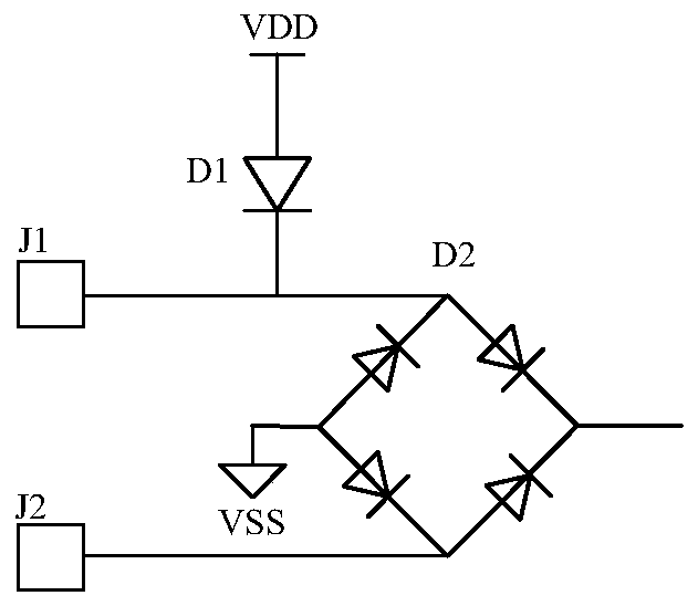
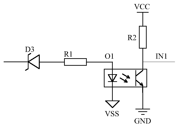
[0029] Such as figure 1 As shown, a digital input circuit suitable for non-polarity multi-level voltage input includes a first digital interface J1 and a second digital interface J2, the first digital interface J1 and the first input terminal of the rectifier bridge D2 Connected, the second switch interface J2 is connected to the second input of the rectifier bridge D2; the first input of the rectifier bridge D2 is connected to the cathode of the diode D1, the anode of the diode D1 is connected to the first power supply VDD, and the first input of the rectifier bridge D2 The two input terminals ar...


PUM


Abstract

The invention discloses a switching value input circuit suitable for non-polar multi-level voltage input, which comprises a first switching value interface and a second switching value interface, thefirst switching value interface is connected with a first input end of a rectifier bridge, and the second switching value interface is connected with a second input end of the rectifier bridge; the first input end of the rectifier bridge is connected with the cathode of the diode; the anode of the diode is connected with a first power supply; the second input end of the rectifier bridge is connected with the second input end of the logic gate device through the second optocoupler isolation sampling circuit, the first output end of the rectifier bridge is connected with the first input end of the logic gate device through the first optocoupler isolation sampling circuit, and the second output end of the rectifier bridge is electrically connected with the first electrical appliance. A circuit design scheme with wide compatibility is provided for information acquisition of the switching value nodes, the connection polarity of the switching value nodes does not need to be considered, and the circuit is suitable for information acquisition of the switching value nodes of multiple levels.

Description

Technical field [0001] The invention relates to the technical field of digital signal acquisition of secondary equipment in intelligent substations, and in particular to a switch input circuit suitable for non-polar multi-level voltage input. Background technique [0002] With the rapid development of smart grids in my country, there are more and more switches in the integrated automation system of substations. The collected signals include the trip position signals of circuit breakers, isolating switches, and grounding switches, the position signals of transformer taps, and various Relay protection, automatic device action signal, etc. [0003] At present, the traditional information collection method of switching value nodes is to rely on the conduction state of the optocoupler to determine the status of the switching value node. The acquisition circuit can only collect information for the state of a single level switching value, and the acquisition circuit needs Strictly require...

Claims


Application Information

Patent Timeline
IPC IPC(8): H03K17/78G01R31/327
CPCH03K17/78G01R31/327Y02B70/10
Inventor 罗建平田坤杨经超周坤王义波孙祥波
Owner WUHAN KEMOV ELECTRIC
Why Eureka
Try Eureka