
Vision-based two-dimensional plane ranging device and method, and marker point recognition device

A two-dimensional plane and distance measuring device technology, applied in the field of visual measurement, can solve the problems of limited measurement range, small range and high cost

Active Publication Date: 2022-04-15
HEBEI UNIV OF TECH
View PDF12 Cites 0 Cited by
  • Summary
  • Abstract
  • Description
  • Claims
  • Application Information

AI Technical Summary

Problems solved by technology

[0003] It can be seen that the existing distance measuring method has the following disadvantages: the measurement dimension is single, and only one-dimensional length can be measured. It is difficult for the traditional distance measuring device to have both range and accuracy. The measurement range of the tool is generally relatively small, and the measurement tools with a large range have low accuracy, such as vernier calipers and tape measures, while laser or ultrasonic distance measurement tools that use electronic technology, because light and sound waves will attenuate with the transmission distance, when When the measurement distance is long, the error will increase, and the cost of these two solutions is relatively high
Although the distance measuring wheel has no range limit in theory, the distance measuring wheel will change the wheel radius due to friction, and the error will increase after long-distance measurement
Most of the existing distance measurement schemes are contact measurement, the measurement process is slow, there are many errors introduced by humans, and the measurement accuracy is within the visible range of the human eye, which is extremely limited; the measurement accuracy of the fourth type of distance measurement method is higher than that of the first three It has been improved a lot and can reach the pixel level or even sub-pixel level, but this method has high requirements on the camera and measurement environment, and the measurement range is extremely limited due to the influence of the camera field of view

Method used


Image

  • Vision-based two-dimensional plane ranging device and method, and marker point recognition device
  • Vision-based two-dimensional plane ranging device and method, and marker point recognition device
  • Vision-based two-dimensional plane ranging device and method, and marker point recognition device

Examples


Embodiment Construction

[0042] In order to make the object, technical solution and advantages of the present invention clearer, the implementation manner of the present invention will be further described in detail below in conjunction with the accompanying drawings.

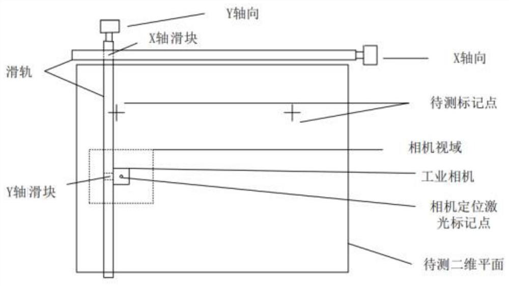
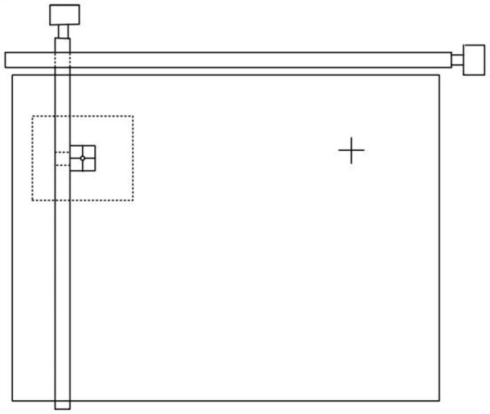
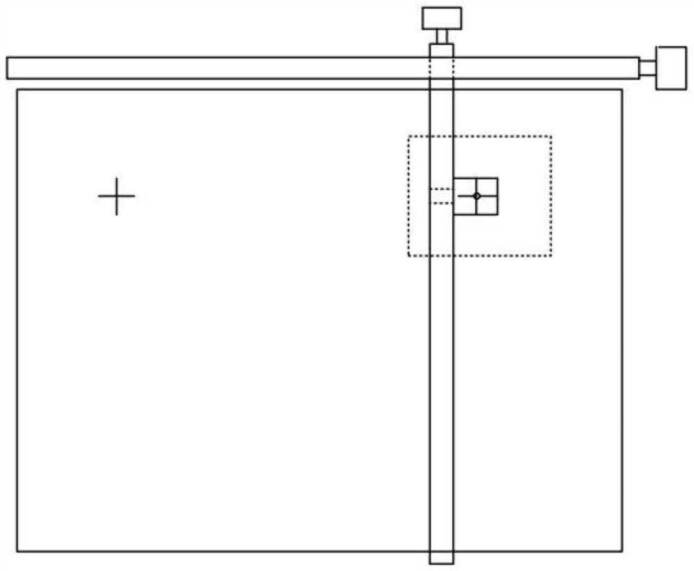
[0043] A vision-based two-dimensional plane distance measuring device of the present invention includes a laser cursor generator, and the laser cursor generator vertically projects a visible laser cursor onto the two-dimensional plane; It is used to converge the projection of the object to be detected in the two-dimensional plane onto the camera target surface; one end of the Y-axis slide rail is fixed on the X-axis slide rail slider, and the industrial camera is fixedly installed on the Y-axis slide rail slider. converting images into digital information for computer processing;

[0044] The computer recognizes the mark points through image preprocessing, and then simultaneously calculates the pixel coordinates of the recognized mark ...


PUM


Abstract

The invention is a vision-based two-dimensional plane ranging device and method, and a marking point recognition device. The distance measuring device includes: a two-dimensional measuring platform; a group of XY moving plane right-angle robots; an industrial camera used for marking point recognition and distance measurement between mark points is connected to the slider of the right-angle robot; an industrial camera is attached for Coordinate positioning laser cursor generator, the laser cursor generator vertically projects a visible laser to the two-dimensional plane to be measured, and moves with the camera. The invention has the characteristic that the measurement area is not limited by the field of view of the camera, and is also not affected by the error of the installation height of the camera.

Description

technical field [0001] The invention belongs to the technical field of visual measurement, and relates to a vision-based two-dimensional plane ranging device and method, and a marking point recognition device. Background technique [0002] Distance measurement is often used in engineering construction and measurement calculations. At present, there are mainly four mainstream distance measurement methods. The first is the reference comparison method. The standard length can be copied and compared with the measured object through a scaled length measurer, such as a ruler, tape measure and other measuring tools. ; The second is to use laser, ultrasonic, etc. to convert the distance information into the time of light or sound wave propagation for measurement; the third is to use the distance measuring wheel or encoder to convert the length of the measured object into the circumference of the distance measuring wheel Multiple perimeters, distance measurement by counting; the fou...

Claims


Application Information

Patent Timeline
Patent Type & Authority Patents(China)
IPC IPC(8): G01B11/00G01B11/03G06K9/62G06T5/00G06T5/40G06T7/00G06T7/13G06T7/62G06T7/80G06V10/74
CPCG01B11/002G01B11/03G06T7/001G06T7/13G06T7/62G06T5/40G06T5/002G06T7/80G06T2207/10004G06T2207/20032G06T2207/30108G06V10/751
Inventor 陈曦张翠杰张少波杨一帆
Owner HEBEI UNIV OF TECH
Learn More