
Cusped magnetic field plasma thruster

A plasma and tangent magnetic field technology, applied in the field of plasma thrusters, can solve the problems of insufficient ionization of gas working fluid and slow heat dissipation in the air gap, and achieve the effects of avoiding paramagnetic phenomenon, improving life, and avoiding magnetic tip phenomenon

Inactive Publication Date: 2020-08-14
金群英
View PDF0 Cites 3 Cited by
  • Summary
  • Abstract
  • Description
  • Claims
  • Application Information

AI Technical Summary

Problems solved by technology

[0006] The invention mainly aims to solve the technical problems that the gas working medium cannot be fully ionized at the wall of the channel, and the air gap between the outer wall of the magnet and the inner wall of the ceramic channel is slow to dissipate heat

Method used


Image

  • Cusped magnetic field plasma thruster
  • Cusped magnetic field plasma thruster
  • Cusped magnetic field plasma thruster

Examples


Embodiment Construction

[0031] The present invention will be further described below in conjunction with the accompanying drawings and embodiments.

[0032] Due to the complex movement trajectories of electrons and ions in the ionization channel of the tangential magnetic field plasma thruster in the electric field and magnetic field, it is greatly affected by the inner wall structure of the ionization channel, so a large number of analysis and experimental studies are required for different channel sections .

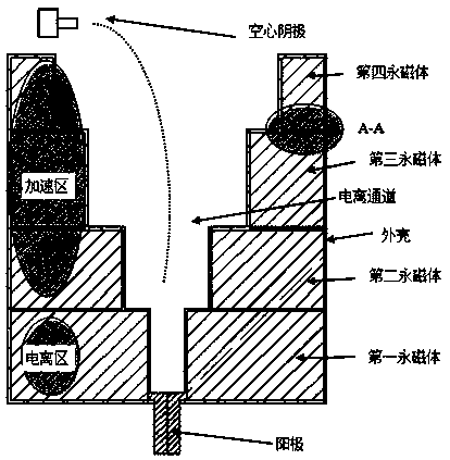
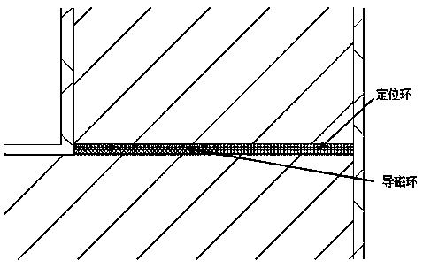
[0033] Such as figure 1 As shown, the tangential field plasma thruster of the present invention includes an ionization channel, a permanent magnet, an anode, a hollow cathode, a magnetically permeable ring, a positioning ring and a casing, an anode is provided at the bottom of the ionization channel, and a hollow cathode is provided at the outlet. The area between the outer wall of the ionization channel and the outer shell is sequentially provided with first, second, third and fourth perman...


PUM


Abstract

The invention relates to a cusped magnetic field plasma thruster. The technical problems to be solved are that a gas working medium cannot be sufficiently ionized at the position of a passageway wallface and cooling of a gas gap between the outer walls of magnets and the inner wall of a ceramic passageway is slow. In order to solve the technical problems, the thruster comprises an ionization passageway, permanent magnets, an anode, a hollow cathode, magnetic conductive rings, positioning rings and a shell. The longitudinal section of the side wall of the side, along the ionization passageway,of each permanent magnet is in a right trapezoid shape or a rectangular shape, and therefore the inner diameter, in the direction from the bottom of the ionization passageway to an outlet, of the ionization passageway is increased in a sequential discrete stair manner. Due to the adoption of the structure, electrons reciprocating between two magnetic tips at a high speed can be sufficiently ionized, and the technical effect that the gas working medium utilization rate is high is achieved. According to the cusped magnetic field plasma thruster, by arranging a heat exchange device on the thruster, the temperature of the gas gap between the outer walls of the magnets and the inner wall of the ceramic passageway is lowered, the paramagnetic phenomenon caused by the fact that temperature of the permanent magnets is too high is avoided, and the service life of the thruster is prolonged.

Description

technical field [0001] The invention relates to the technical field of tangent magnetic field plasma propulsion, in particular to a tangent magnetic field plasma thruster with a special cross-sectional channel. Background technique [0002] This application is a divisional application, and the parent application number is CN 201910119891.5. [0003] The tangential magnetic field plasma thruster is an advanced electric propulsion device, which is widely used in the field of satellite position maintenance and attitude control, and is known as the first choice for future space vehicles due to its simple structure, high specific impulse, and high efficiency. One of the propulsion devices. [0004] When electrons are emitted from the cathode at the exit of the channel and move toward the anode along the channel axis, due to the magnetic confinement and the magnetic mirror effect of the magnetic tip, it is difficult for the electrons to reach the straight channel wall in the tang...

Claims


Application Information

Patent Timeline
Patent Type & Authority Applications(China)
IPC IPC(8): F03H1/00
CPCF03H1/0031F03H1/0081
Inventor 金群英
Owner 金群英
Learn More