Reel hoisting mechanism with wire head treatment function

A hanging plate and wire head technology, applied in the field of enameled wire manufacturing equipment, can solve the problems of scratches, unfavorable full automation, complex structure, etc.

Pending Publication Date: 2020-08-14
WUXI JUYI TONGCHUANG TECH CO LTD
View PDF0 Cites 1 Cited by
  • Summary
  • Abstract
  • Description
  • Claims
  • Application Information

AI Technical Summary

Problems solved by technology

Some defects were found after use: First, before winding the empty reel, the end of the thread is usually fixed in the wire catcher before winding, then the end of the thread needs to be disengaged after the reel is full, the current reel transfer manipulator does not It has this automatic operation; secondly, after the thread end slips off, it becomes a free end, which is easy to scratch the surface of the wound thread, and after the thread tail is cut off, it will also become a free end, which will also scratch the surface of the wound thread; The third is that the existing wire reel transfer manipulator grabs from the outside of the wire reel, and the grasp is unstable, which often requires manual correction, which cannot meet the high-speed production requirements, is not conducive to the realization of full automation, and has a complex structure and requires a relatively large space; Fourth, the scope of application of the equipment is small, and the parts of the equipment need to be replaced for plates of different sizes, which is costly

Method used


Image

  • Reel hoisting mechanism with wire head treatment function
  • Reel hoisting mechanism with wire head treatment function
  • Reel hoisting mechanism with wire head treatment function

Examples


Embodiment 1

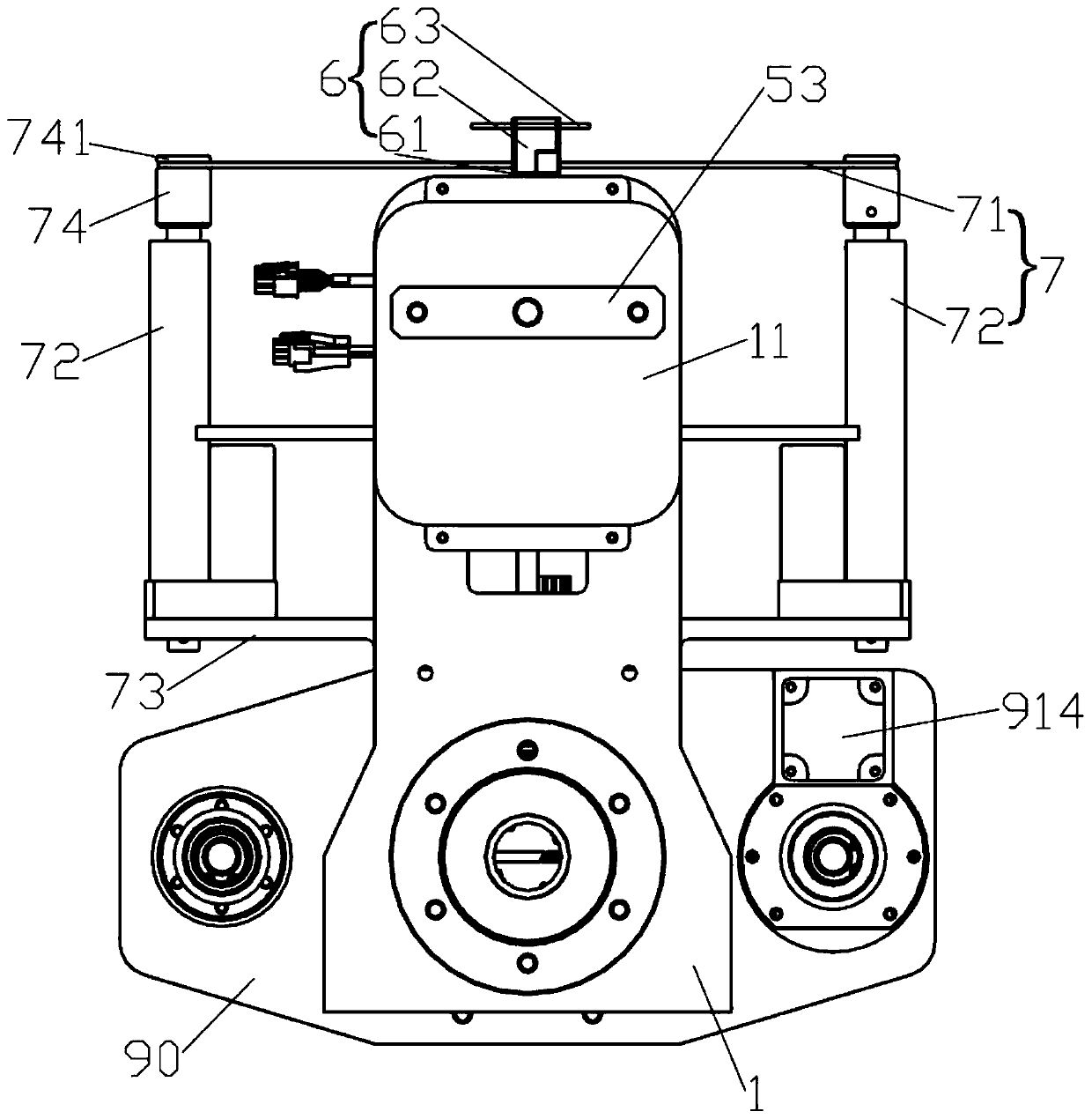
[0046] Such as Figures 1 to 4 As shown, the hanging pan mechanism with thread end processing according to one embodiment of the present invention includes a base 1 , a thread end processing device disposed at one end of the base 1 , and a hanging pan grasping device disposed at the other end of the base 1 . The base 1 is equipped with a fixed sleeve positioning ring 20 through bolts, and the fixed sleeve positioning ring 20 is located directly above the hanging pan grabbing device. The fixed sleeve positioning ring 20 is used to connect the manipulator to realize the connection between the suspension pan mechanism and other equipment parts. Cooperate.

[0047] The hanging pan grabbing device includes a fixed sleeve 2 and a suspension pan shaft 3. The top of the fixed sleeve 2 is fixedly connected to the lower surface of the base 1 by bolts. The fixed sleeve 2 is a hollow structure, and the lower part of the fixed sleeve 2 is sleeved on the suspension pan shaft. 3 outside the...

Embodiment 2

[0061] Such as Figures 11 to 16 As shown, the main difference between the hanging plate mechanism with thread end processing described in Embodiment 2 and Embodiment 1 is that the control shaft driver 80 for driving the control shaft 8, the lifting mechanism for driving the plate tool pressing plate 9, and the driving off-line top 5 The off-line drivers are different. In this embodiment, pneumatic control is mainly used.

[0062] Such as Figure 17 with 18 As shown, the control shaft driver 80 is a cylinder 80B. The cylinder body of the cylinder 80B is installed on the top of the suspension pan shaft 3 . The piston rod of the cylinder 80B is connected to the top of the control shaft 8 . When the cylinder 80B is used as the control shaft driving member 80, the up and down movement of the control shaft 8 relative to the suspension pan shaft 3 is realized through the expansion and contraction of the piston rod of the cylinder 80B. Specifically, when the piston rod of the cyl...


PUM


Abstract

The invention discloses a reel hoisting mechanism with a wire head treatment function. The reel hoisting mechanism comprises a base, a wire head treatment device arranged at one end of the base, and areel hoisting and grabbing device arranged at the other end of the base. The reel hoisting and grabbing device comprises a fixed sleeve and a reel hoisting shaft. The top of the fixed sleeve is connected to the base. The upper portion of the reel hoisting shaft is connected with the lower portion of the fixed sleeve. The outer wall of the reel hoisting shaft is provided with a hinge block assembly capable of stretching out or drawing back. The wire head treatment device comprises a wire release center, a wire hooking assembly and a wire pressing assembly. The wire release center is liftably and movably connected to the base. The wire hooking assembly is arranged on the outer side of the wire release center. The wire pressing assembly can stretch out or draw back and is loc below the wirehooking assembly. The reel hoisting mechanism is compact in structure, realizes automatic release of a wire head, can fix the wire head and the wire tail after wire release cannot scratch the surfaceof a wound wire, hooks a reel from a center hole of the reel through the retractable hinge block assembly, is stable in reel hoisting and achieves the automatic transfer effect of the reel.

Description

technical field [0001] The invention relates to enameled wire manufacturing equipment, more specifically to a suspension pan mechanism with wire end processing. Background technique [0002] The enameled wire is composed of the inner wire and the coating that wraps the wire. During the production process of the enameled wire, the wire needs to be wound on the wire reel by a wire take-up device. After the wire reel is wound, it is necessary to transfer the full reel in time to replace it with an empty reel in time. [0003] At present, some of the switching and transfer of full or empty reels are operated purely manually, and some of them are equipped with a manipulator on the conveying line to grab the wire reel. Some defects were found after use: First, before winding the empty reel, the end of the thread is usually fixed in the wire catcher before winding, then the end of the thread needs to be disengaged after the reel is full, the current reel transfer manipulator does ...

Claims


Application Information

Patent Timeline
IPC IPC(8): B65H67/04B65H65/00B66C1/62B66C13/06
CPCB65H65/005B65H67/0411B65H2701/36B66C1/625B66C13/06
Inventor 张伟新蔡麟梁骁军郎宁卡
Owner WUXI JUYI TONGCHUANG TECH CO LTD
Why Eureka
Try Eureka