Agricultural pinecone threshing farm machine device
A pine cone and agricultural machinery technology, applied in the field of agricultural pine cone threshing agricultural machinery, can solve the problems of poor threshing effect and low efficiency, and achieve the effect of improving work efficiency and strengthening screening efficiency
- Summary
- Abstract
- Description
- Claims
- Application Information
AI Technical Summary
Problems solved by technology
Method used
Image
Examples
specific Embodiment approach 1
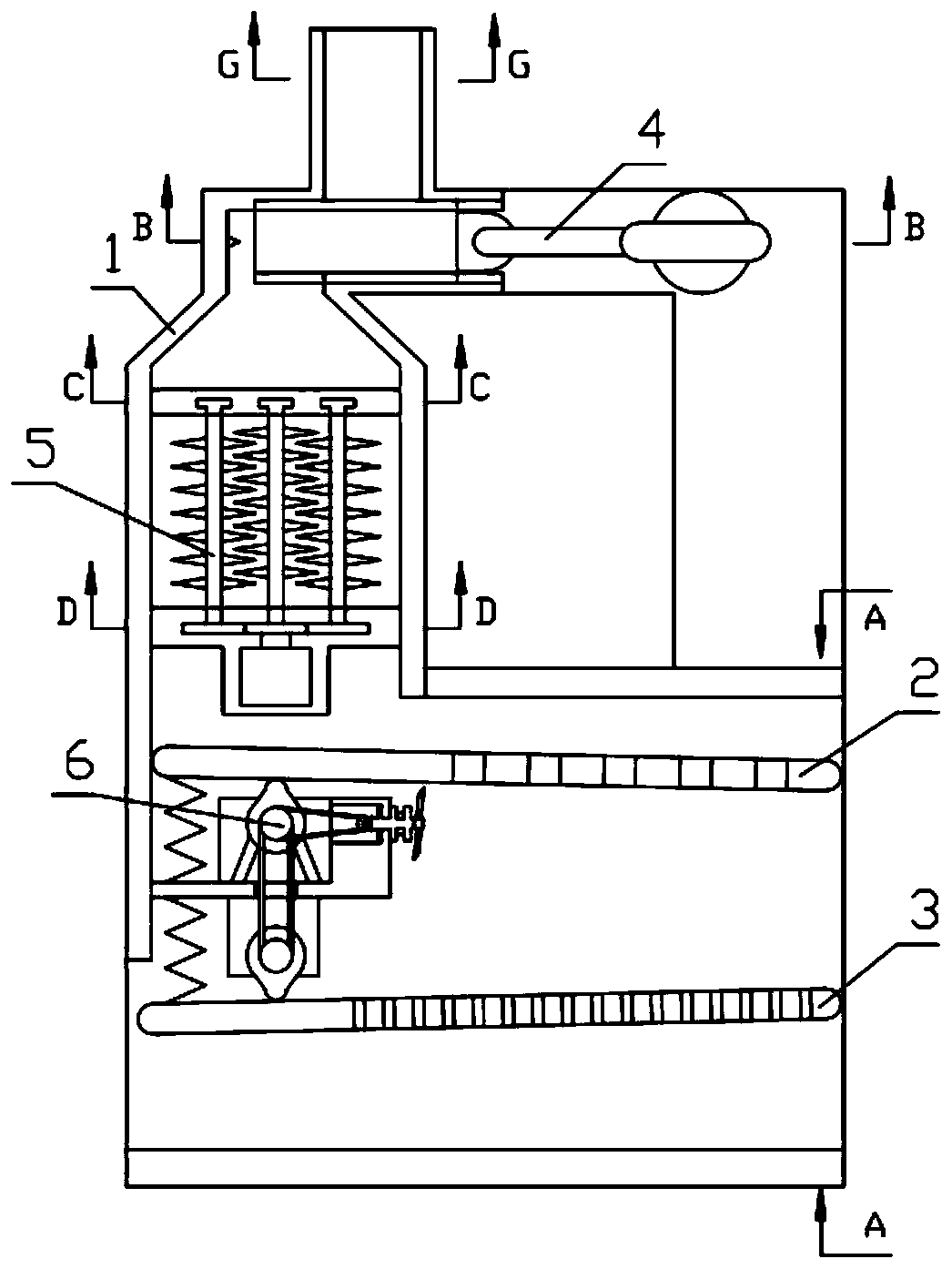
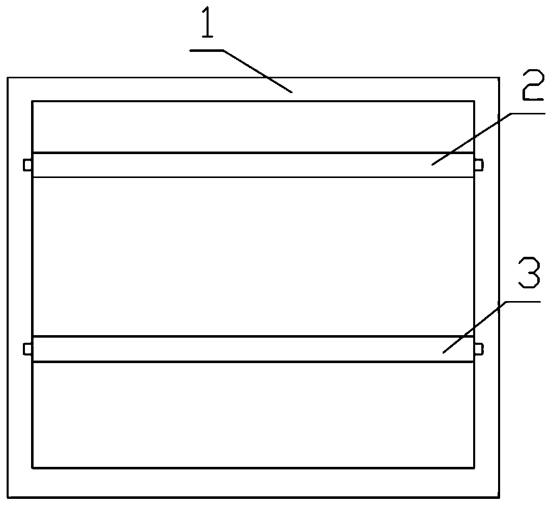
[0032] Combine below Figure 1-10 Illustrate this embodiment, a kind of agricultural pine cone threshing agricultural machinery device, comprises device casing 1, sieve plate one 2 and sieve plate two 3, and sieve plate one 2 is rotatably installed on the groove that is provided on device box body 1, and sieve plate 2. 3 rotations are mounted on the groove provided on the device box 1, the pine cone extruding mechanism 4, the pine cone breaking up mechanism 5 are fixedly installed on the device box 1, and the pine nut screening mechanism 6 is fixedly installed on the device On the box body 1, the pine nut screening mechanism 6 is connected with the sieve plate one 2, the pine nut screening mechanism 6 is connected with the sieve plate two 3, and the pine cone extruding mechanism 4 is installed on the device box body 1.
specific Embodiment approach 2
[0034] Combine below Figure 1-10 Illustrate this embodiment, this embodiment will further explain embodiment one, described pine cone extruding mechanism 4 comprises crankshaft motor 4-1, stopper 4-2, crankshaft 4-3, swing lever 4-4, loose Tower extrusion 4-5, positioning cone 4-6, crankshaft motor 4-1 is fixedly installed on the device box 1, and the limiter 4-2 is rotatably installed in the through hole provided on the device box 1 and fixed Installed on the output end of the crankshaft motor 4-1, one end of the crankshaft 4-3 is fixedly installed on the limiter 4-2, and the other end of the crankshaft 4-3 is rotatably installed on the groove provided on the device box 1, swinging One end of the rod 4-4 is rotatably mounted on the crankshaft 4-3, the other end of the swing rod 4-4 is hinged with the pine cone extrusion 4-5, and the pine cone extrusion 4-5 is slidably installed in the device box 1 On the through hole provided above, the positioning cone 4-6 is fixedly insta...
specific Embodiment approach 3
[0036] Combine below Figure 1-10Describe this embodiment, this embodiment will further explain Embodiment 1, and described pine cone breaking mechanism 5 comprises upper slat 5-1, toothed main shaft 5-2, main gear 5-3, main motor 5-4 , pinion gear 5-5, toothed auxiliary shaft 5-6, lower slat 5-7, upper slat 5-1 is fixedly installed on the device box 1, and lower slat 5-7 is fixedly installed on the device box 1 On the top, the toothed main shaft 5-2 is rotatably installed on the groove provided on the upper slat 5-1, and the toothed auxiliary shaft 5-6 is rotatably installed on the groove provided on the upper slat 5-1, and the toothed main shaft 5-2 is fixedly installed on the main gear 5-3, and the main gear 5-3 is fixedly installed on the output end of the main motor 5-4, and the main motor 5-4 is fixedly installed in the groove of the lower slat 5-7, and the auxiliary gear 5-5 is fixedly connected with the toothed auxiliary shaft 5-6, the main gear 5-3 meshes with the au...
PUM
 Abstract
Description
Claims
Application Information
 - R&D
- Intellectual Property
- Life Sciences
- Materials
- Tech Scout
- Unparalleled Data Quality
- Higher Quality Content
- 60% Fewer Hallucinations
Browse by: Latest US Patents, China's latest patents, Technical Efficacy Thesaurus, Application Domain, Technology Topic, Popular Technical Reports.
© 2025 PatSnap. All rights reserved.Legal|Privacy policy|Modern Slavery Act Transparency Statement|Sitemap|About US| Contact US: help@patsnap.com


