
Intelligent camera

A smart camera and camera technology, applied in the field of smart cameras, can solve problems such as shortening the service life of the connector, lack of automatic cleaning, and pollution of the connector, achieving the effects of saving manpower, prolonging life, and being safe and convenient to use

Active Publication Date: 2020-08-11
BEIJING ZHONGTAI HAOMIAO TECH DEV
View PDF11 Cites 1 Cited by
  • Summary
  • Abstract
  • Description
  • Claims
  • Application Information

AI Technical Summary

Problems solved by technology

In the process of using the device, the inventor found that the storage box of the device is used as a container for placing the connector when the camera is idle, and lacks the function of automatic cleaning. If the storage box enters a lot of dust and other sundries during the use of the camera, When the connector is stored in the storage box, it is easy to pollute the exposed metal part of the connector and shorten the service life of the connector

Method used


Image

  • Intelligent camera
  • Intelligent camera
  • Intelligent camera

Examples


Embodiment

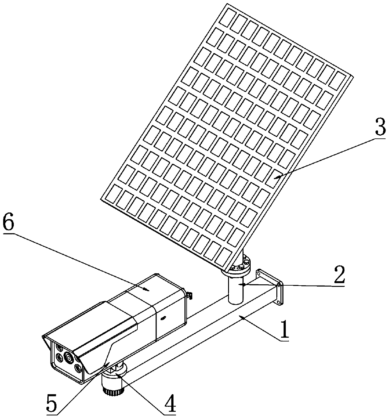
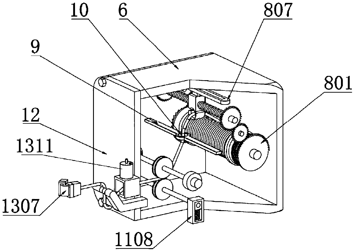
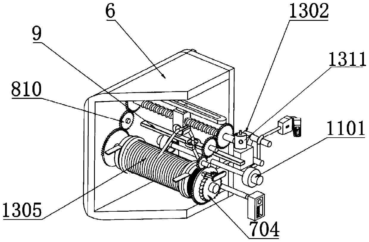
[0038] Example: such as Figure 1-11 As shown, the present invention provides a technical solution, a smart camera, including a mounting horizontal frame 1, a connecting rod 2 is fixedly connected to the middle of the top of the mounting horizontal frame 1, a solar panel 3 is fixedly connected to the top of the connecting rod 2, and the horizontal frame is installed 1. One side of the top is rotatably connected to the connecting disc 4, and the top of the connecting disc 4 is rotatably connected to the camera body 5. One end of the camera body 5 is fixedly connected to the take-up box 6, and one side of the take-up box 6 is rotatably connected to an active take-up mechanism. 7;

[0039]The active take-up mechanism 7 includes a support crossbar 701, a take-up roller 702, a scroll spring 703, a limit ratchet 704, a toggle piece 705, a transmission thin shaft 706, a limit ring 707 and a limit swing block 708;

[0040] One side of the take-up box 6 is rotatably connected with a s...


PUM


Abstract

The invention discloses an intelligent camera. One side of a take-up box is fixedly connected with a sealing cover plate, the upper end of the storage square box is fixedly connected with a micro compressed air cylinder, the upper end of the micro compressed air cylinder is communicated with a one-way inflation valve, the lower end of the micro compressed air cylinder is communicated with the upper end of the storage square box through a sweeping pipe, an electromagnetic valve is arranged in the sweeping pipe, and a pressure gauge is arranged on the micro compressed air cylinder; a concave fixed shaft is arranged in the middle of the upper guide column; the fixed shaft is sleeved with a rotary drum, a first infrared sensor and a second infrared sensor are fixedly embedded in the wall surface close to one side of the fixed bent rod, an infrared emitter is fixedly embedded in the surface, facing the first infrared sensor and the second infrared sensor, of the rotary drum, and the included angle between the first infrared sensor and the second infrared sensor is not greater than 40 degrees; and a controller is fixed on the micro compressed air cylinder, receives signals of the first infrared sensor and the second infrared sensor and controls the action of the electromagnetic valve.

Description

technical field [0001] The invention relates to the technical field of security monitoring devices, in particular to an intelligent camera. Background technique [0002] The security monitoring system uses optical fiber, coaxial cable or microwave to transmit video signals in its closed loop, and forms an independent and complete system from camera to image display and recording. It can reflect the monitored objects in real time, vividly and truly. It not only greatly extends the observation distance of the human eye, but also expands the function of the human eye. It can replace manual monitoring for a long time in a harsh environment, allowing people to see all the actual situations that are actually happening at the monitored site, and through Recorded by the video recorder, with the continuous development of technology, outdoor security monitoring devices have gradually begun to use solar energy for power supply; [0003] At present, the security monitoring devices on t...

Claims


Application Information

Patent Timeline
Patent Type & Authority Applications(China)
IPC IPC(8): H04N5/225F16M11/04H01R13/72H02J7/35
CPCH01R13/72F16M11/04H02J7/35H04N23/50H04N23/51
Inventor 魏运昌
Owner BEIJING ZHONGTAI HAOMIAO TECH DEV
Learn More