
Screw-based nanometric linear motion control mechanism

A technology of linear motion and control mechanism, applied in the direction of piezoelectric effect/electrostrictive or magnetostrictive motor, generator/motor, transmission device, etc., can solve the problem of screw gap, wear and reduce the accuracy of the mechanism over time And other issues

Pending Publication Date: 2020-08-11
CEDRAT TECH
View PDF4 Cites 1 Cited by
  • Summary
  • Abstract
  • Description
  • Claims
  • Application Information

AI Technical Summary

Problems solved by technology

This thread is subject to a lot of friction, which means it wears, causing play in the screw
This backlash due to wear of the screw can quickly degrade the accuracy of the mechanism over time

Method used


Image

  • Screw-based nanometric linear motion control mechanism
  • Screw-based nanometric linear motion control mechanism
  • Screw-based nanometric linear motion control mechanism

Examples


Embodiment Construction

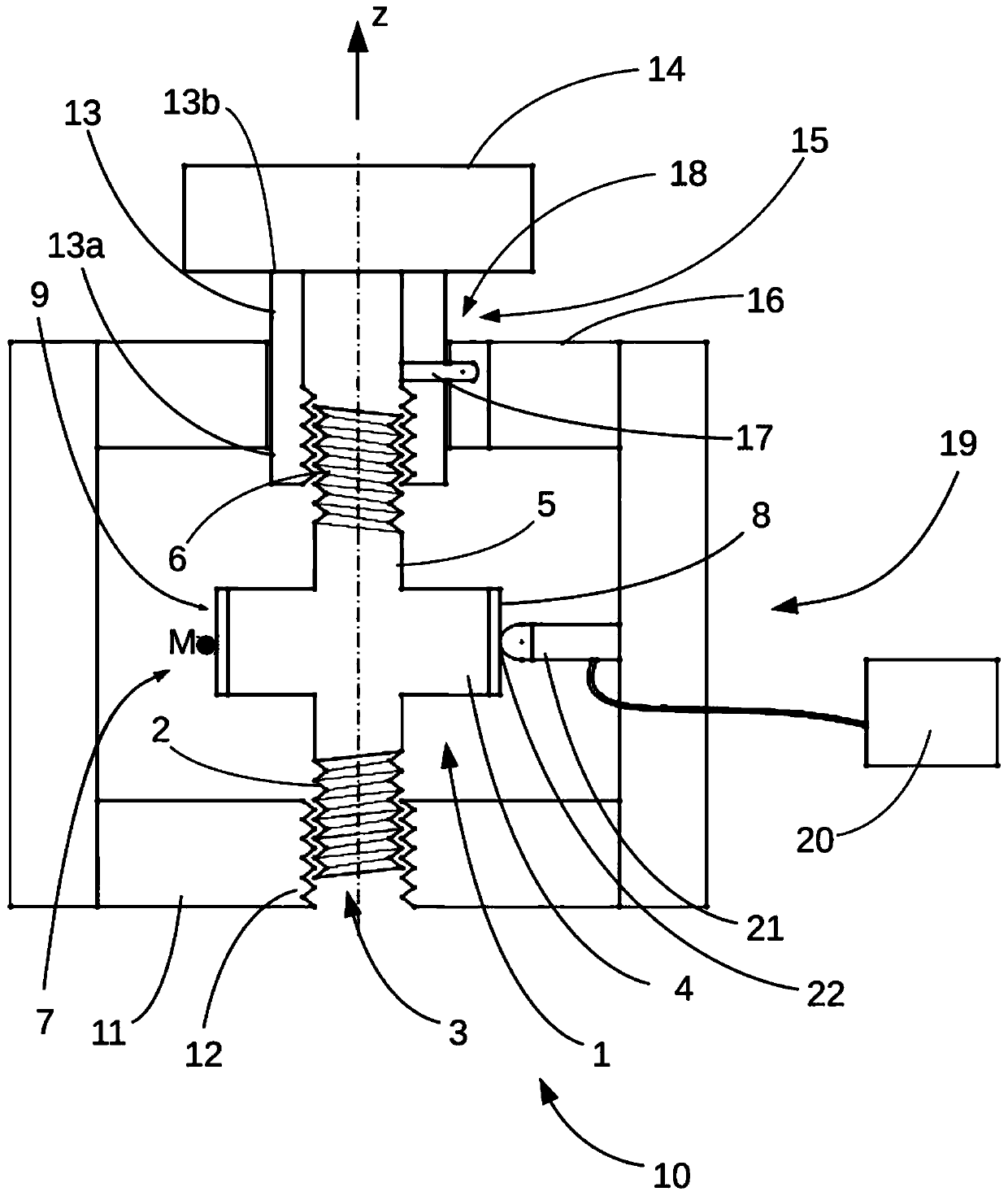
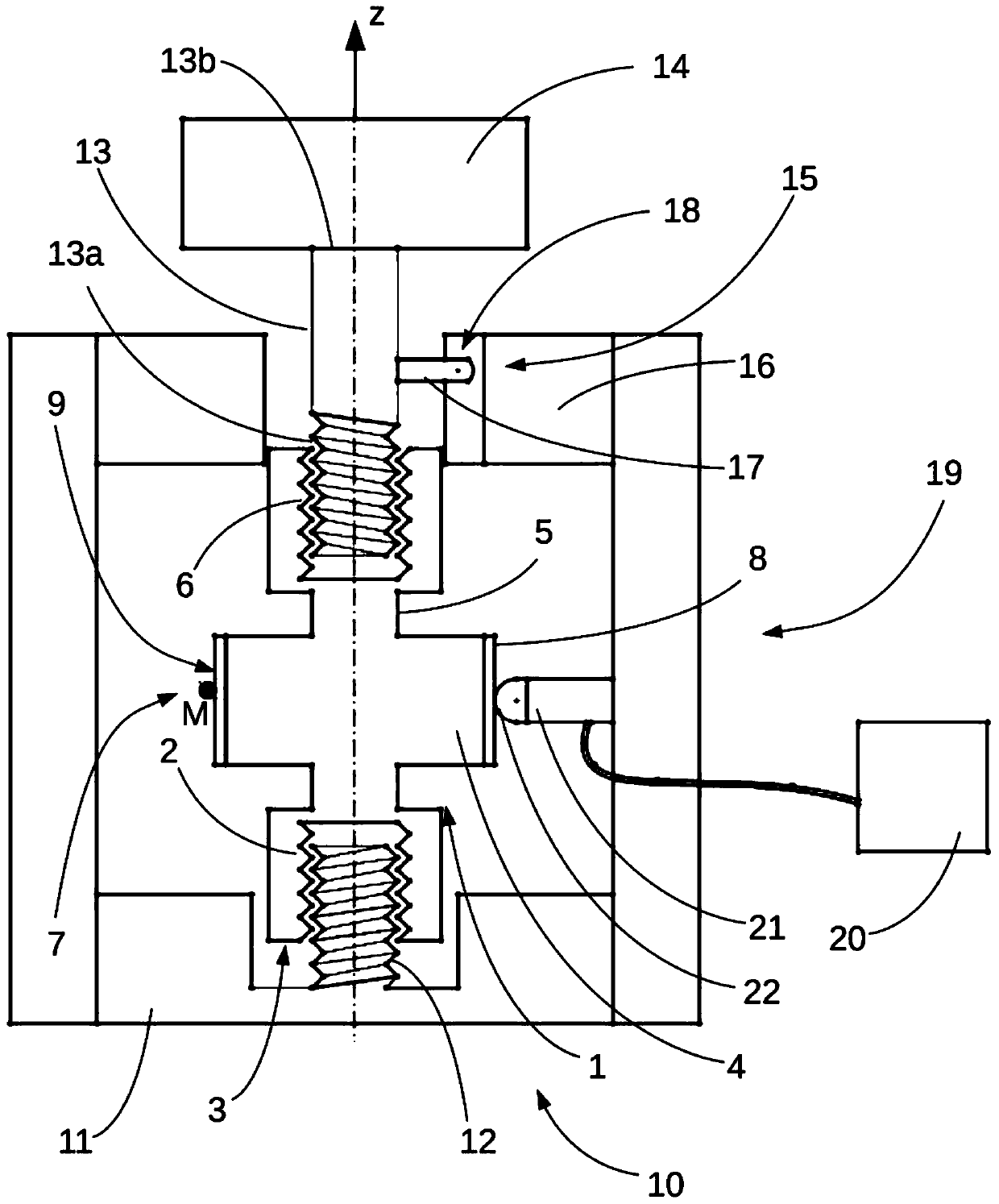
[0055] refer to figure 1 and 2 , the translational motion control mechanism includes a rotor 1, also referred to as a rotor subassembly. The rotor 1 has a first end 3 with a first threaded portion 2 comprising a first thread. The first thread has a first pitch. The second end 5 of the rotor 1 has a second threaded portion 6 comprising a second thread with a second pitch that is the same as or different from the first pitch. figure 1 A first threaded part 2 and a second threaded part 6 are shown, each in the form of a rod with an external thread. figure 2 A first threaded part 2 and a second threaded part 6 are shown, each in the form of a rod with an internal thread or tap. Of course, it is possible to have the rotor 1 threaded at one end and tapped at the other end.

[0056] Between the first and second threaded parts 2 and 6 there is provided a central part 4 which defines an active area 7 of the rotor 1 . The active area 7 has an advantageously circular drive area 9 ...


PUM


Abstract

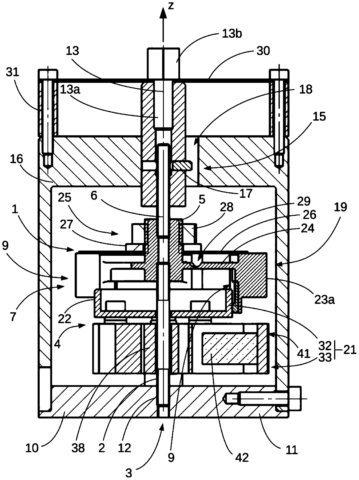
A linear motion control mechanism comprises a rotor (1) mounted rotating around an axis (z). The rotor (1) has a first threaded part (3) and a second threaded part (6) separated by a central part (4)placed in contact with a stator (19) excited by an oscillator (21). A frame (10) defines a first threaded part (12) collaborating with the first threaded part (3) of the rotor (1). The second threadedpart (6) of the rotor (1) collaborates with an output shaft (13). Rotation of the rotor (1) with respect to the frame (10) results in movement of the output shaft (13) along the axis (z). The oscillator (21) comprises an oscillating mass (32) excited by an angular actuator (33) formed by piezoelectric actuators (42) arranged around a star-shaped support (38). The oscillator (21) is fitted insidethe rotor (1) configured in the form of a bell and comprising several stressed sectors (23a).

Description

technical field [0001] The invention relates to a linear positioning mechanism. Background technique [0002] Motor-driven screws are used in the production of linear long-travel positioning actuators to provide fixation in place, for example to perform focusing functions in optics. [0003] The most general concept of an electromechanical actuator with a motor-driven screw is described, for example, in document US2003010146A. Electromechanical actuators consist of a geared motor that rotates a screw that drives a part in the form of a nut in translation, on which the guided moving part is fixed. Rotation of the screw relative to the nut results in translational movement of the nut. [0004] This configuration has some disadvantages. Gear motors are cumbersome components. This results in electromechanical actuators that are often very large and / or very long laterally along the actuation axis. In addition, due to the backlash of the gear motor, the resolution and positio...

Claims


Application Information

Patent Timeline
Patent Type & Authority Applications(China)
IPC IPC(8): H02N2/10H02N2/12H02N2/14H10N30/00
CPCH02N2/10H02N2/126H02N2/12H02N2/14H02N2/101F16H2025/2075F16H2025/204F16H25/20F16H25/24F16H2025/2084G02B26/0858H02N2/02
Inventor F.巴里洛特C.贝利A.吉格纳伯特
Owner CEDRAT TECH
Learn More