


Quick Research
Generate reliable direction feasibility study reports for your R&D in just a few steps.

Technical Q&A
Discover and master advanced knowledge NOW. Basics, ideas, possibilities, all at once.

Find Solutions
As an expert in R&D theories, this can generate solutions to your technical problems instantly.

Evaluate Feasibility
Analyze your overall solution with one click, know your potential R&D risks in advance.

Monitor Landscape
Get weekly tech updates, stay abreast of the latest tech innovations and key insights.
Power switch and automatic walking equipment
A technology of automatic walking equipment and power switches, which is applied in the direction of electric switches, circuits, electrical components, etc., can solve the problems of potential safety hazards and the opening of automatic walking equipment, and achieve the effect of simplifying operations and improving user experience
- Summary
- Abstract
- Description
- Claims
- Application Information
AI Technical Summary
Problems solved by technology
Method used
Image

Examples
Embodiment 1
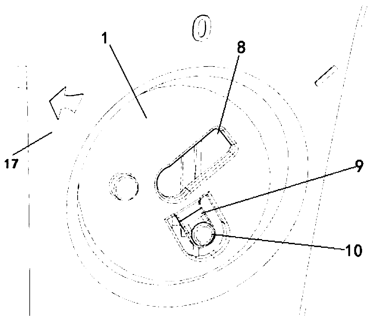
[0056] In this example, refer to Figure 4 As shown, after the key is inserted into the key mounting seat, the key 2 is moved from the storage position to the starting position, and the key 2 performs inward linear movement and rotational movement respectively in sequence.
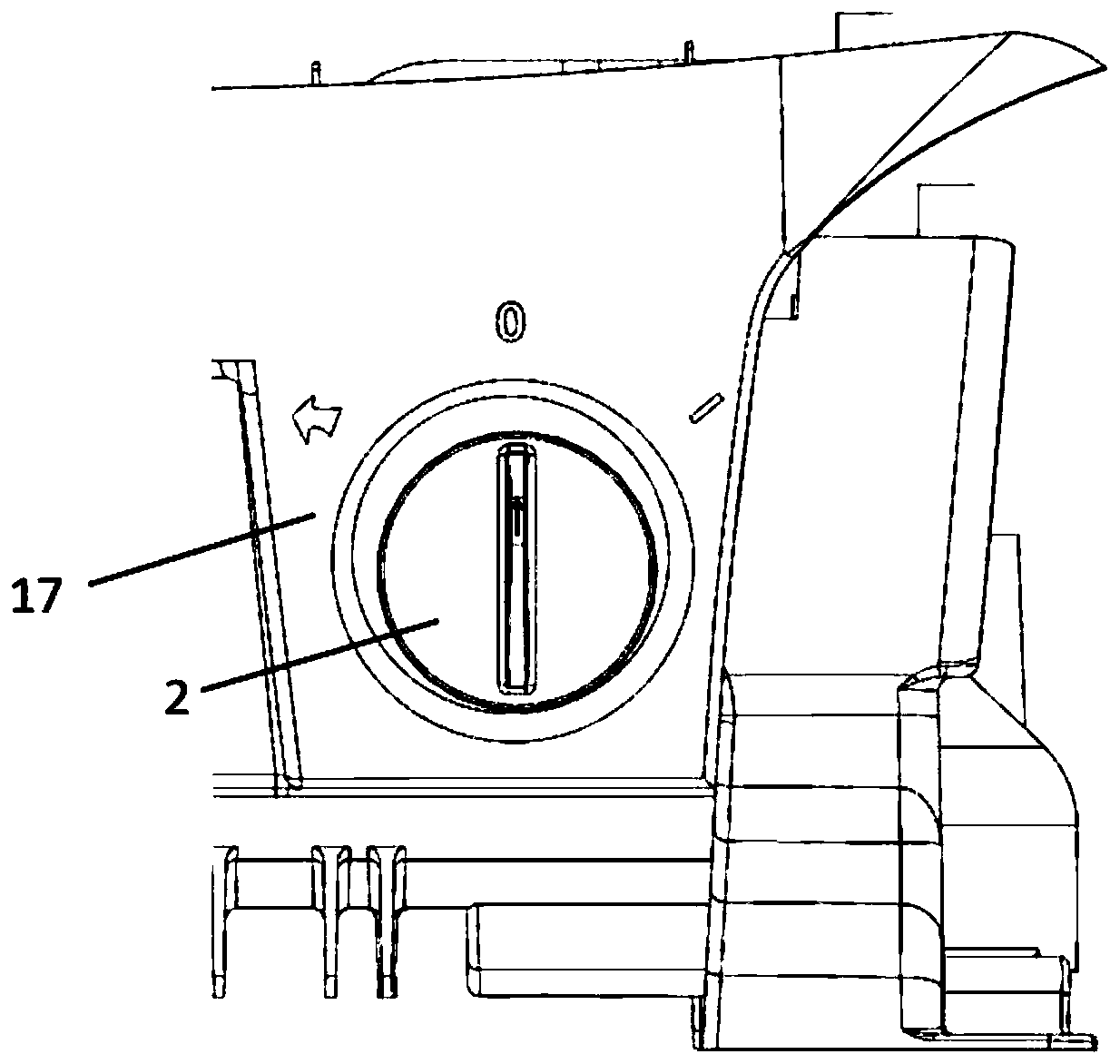
[0057] refer to Figure 1-6 As shown, in the power switch structure in this implementation mode, the power switch can be arranged outside the casing of the automatic walking equipment.
[0058] Figure 1-3 Among them, the automatic equipment represented by the robot lawn mower includes: a casing 17, a key mounting seat 1 arranged on the casing 17, and a key 2 inserted and installed on the key mounting seat 1.
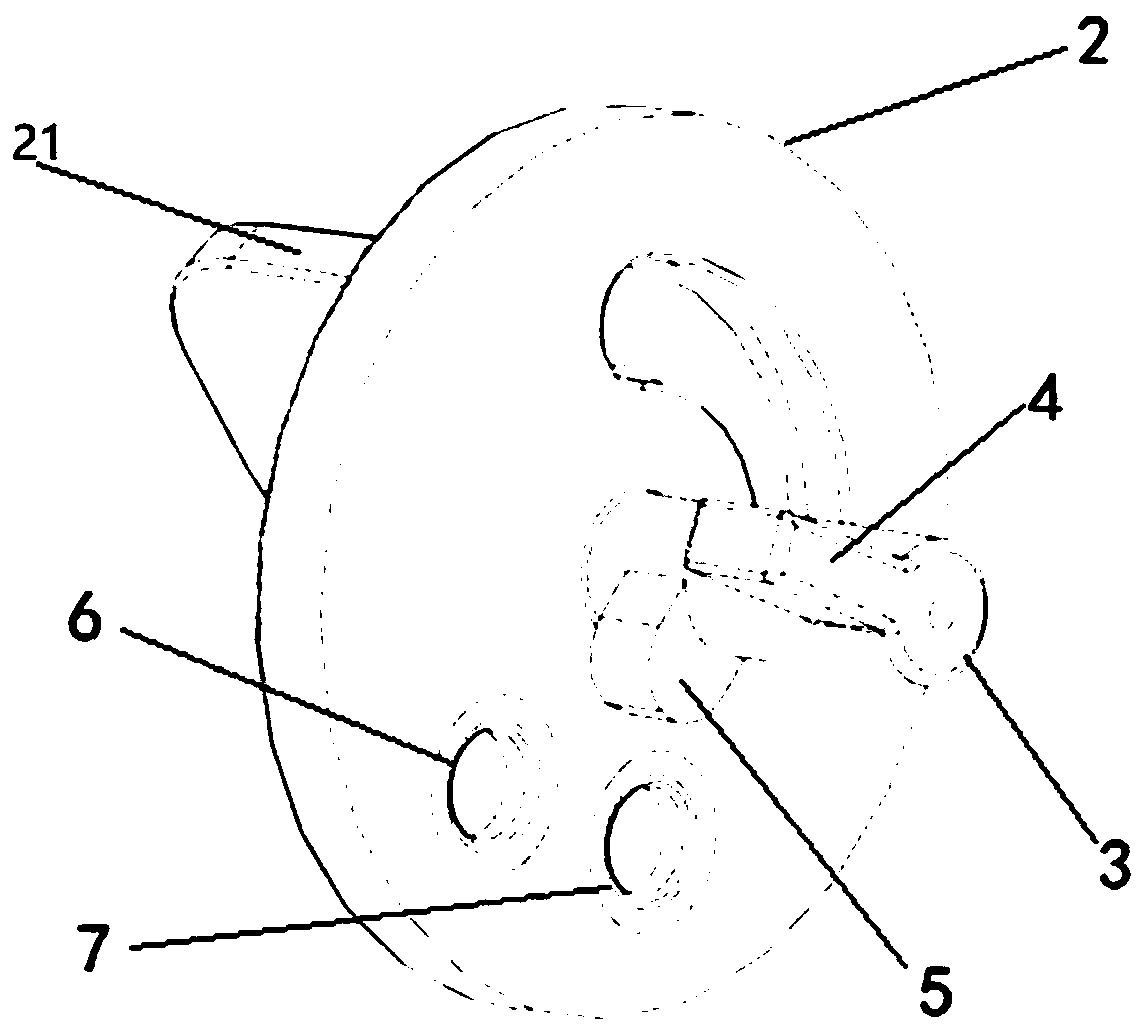
[0059] Among them, the key 2 includes a rotating shaft 3 vertically arranged on the front side of the key connecting plate at the bottom of the key body, a first cantilever 4 and a second cantilever 5 arranged on the rotating shaft 3, wherein a certain distance is provided between the first cantil...
Embodiment 2
[0069] In this embodiment, the key also has three motion positions:
[0070] The first position is the installation position, which refers to the position where the key is inserted into and pulled out of the installation seat. When the key is in this installation position, it can be directly taken out or inserted along the path where it is inserted into the key installation seat 1;
[0071] The second position is an OFF position or a storage position. When the key is in this position, it cannot be taken out directly along the path where it is inserted into the key mounting seat 1 . After the key is plugged into the key mounting seat, it needs to be rotated at a certain angle from the mounting position to reach the OFF position. In this position, the key cannot be pulled out, and the switch is not turned on;
[0072] The third position is the ON position or the starting position. The key is pushed in from the OFF position and fixed at the ON position after a certain angle of r...
PUM
 Abstract
Description
Claims
Application Information
 - R&D Engineer
- R&D Manager
- IP Professional
- Industry Leading Data Capabilities
- Powerful AI technology
- Patent DNA Extraction
Browse by: Latest US Patents, China's latest patents, Technical Efficacy Thesaurus, Application Domain, Technology Topic, Popular Technical Reports.
© 2024 PatSnap. All rights reserved.Legal|Privacy policy|Modern Slavery Act Transparency Statement|Sitemap|About US| Contact US: help@patsnap.com