
Positioning device of spindle bearing pedestal of wind generating set

A technology for wind turbines and spindle bearings, which is applied to workpiece clamping devices, workbenches, manufacturing tools, etc. It can solve problems such as poor clamping stability, residue cleaning jams, and single sliding structure, and achieve rapid adjustment and improved stability. degree of effect

Inactive Publication Date: 2020-08-11
JIAXING UNIV
View PDF1 Cites 0 Cited by
  • Summary
  • Abstract
  • Description
  • Claims
  • Application Information

AI Technical Summary

Problems solved by technology

[0007] In order to solve the above-mentioned technical problems, the present invention provides a positioning device for the main shaft bearing seat of a wind power generating set, to solve the existing problem that the sliding structure has defects. The stability is poor, and it is prone to slight shaking, which leads to the reduction of precision; on the other hand, the trough sliding structure of the existing device cannot realize the cleaning of the residue in the sliding groove during the sliding process, and is prone to jamming; now The sliding structure of the sliding rod of the existing device lacks a protective structure. When a hard object touches the sliding rod, it is easy to cause the outer surface of the sliding rod to deform and cause sliding jamming; moreover, the fixture structure of the existing device cannot adapt to bearings of different diameters at the same time. The clamping of the seat, and the problem of poor clamping stability

Method used


Image

  • Positioning device of spindle bearing pedestal of wind generating set
  • Positioning device of spindle bearing pedestal of wind generating set
  • Positioning device of spindle bearing pedestal of wind generating set

Examples


Embodiment Construction

[0031] Embodiments of the present invention will be further described in detail below in conjunction with the accompanying drawings and examples. The following examples are used to illustrate the present invention, but should not be used to limit the scope of the present invention.

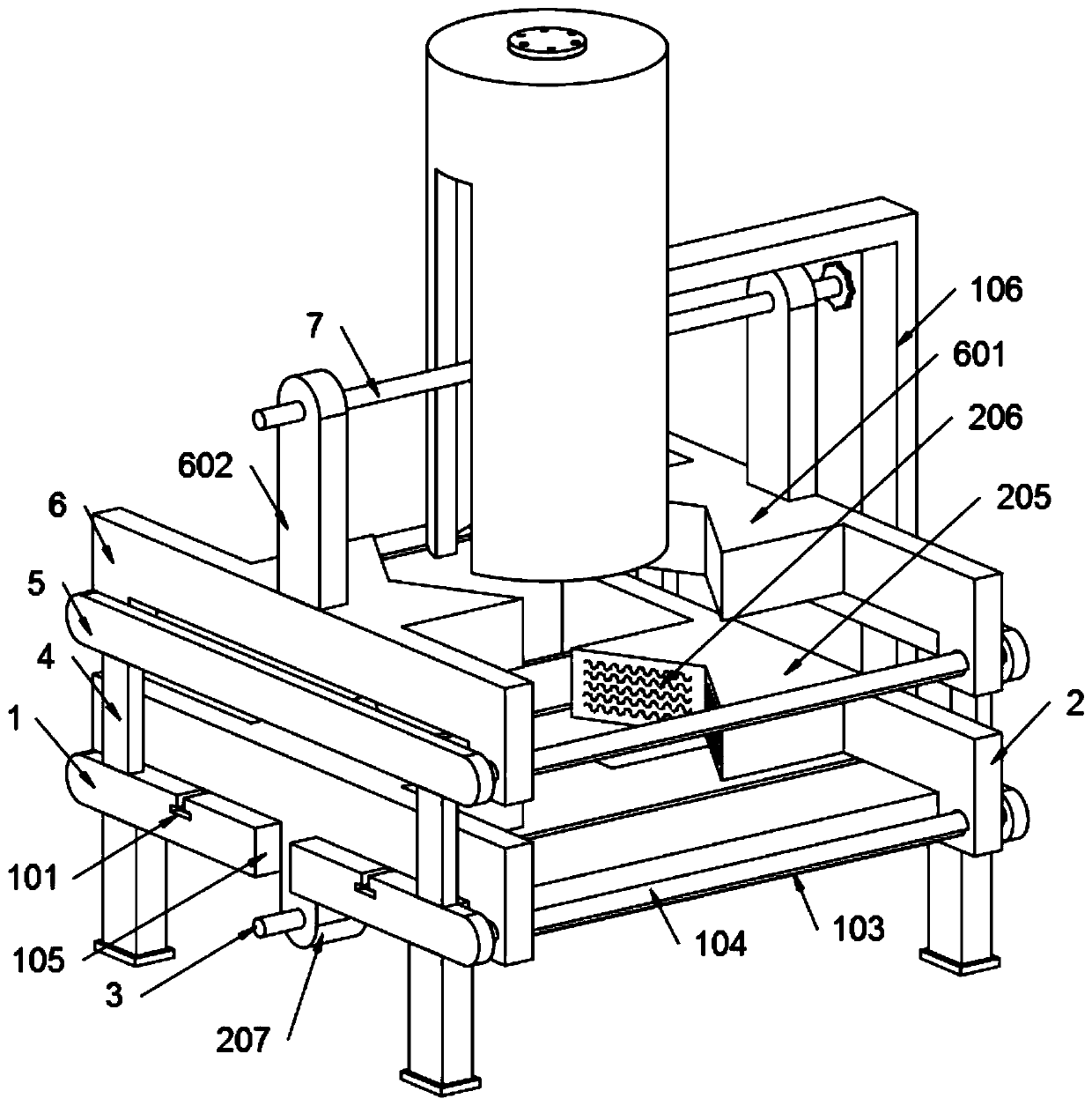
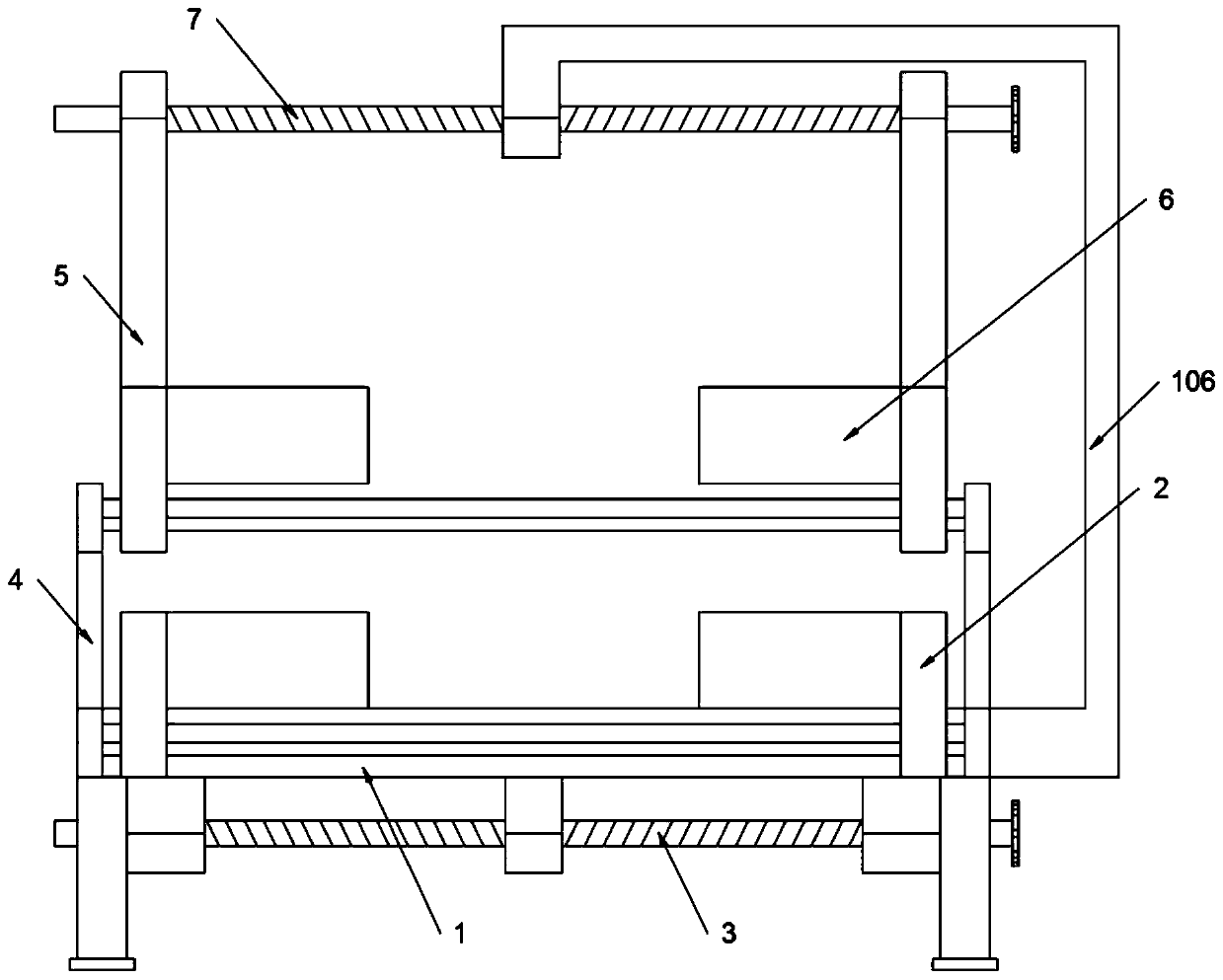
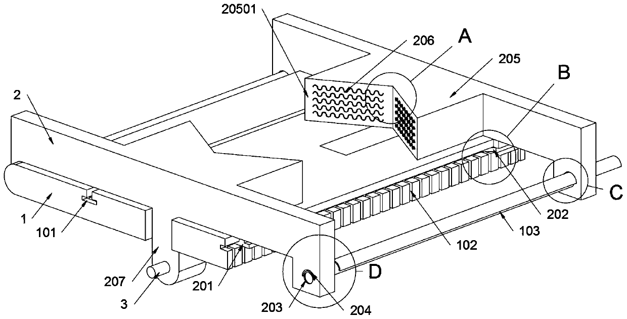
[0032] as attached figure 1 To attach Figure 8 Shown:

[0033] The present invention provides a positioning device for a main shaft bearing seat of a wind power generating set, which includes a main body seat 1; two first clamp seats 2 are slidably connected to the main body seat 1, and an adjusting rod 3 is threadedly connected to the two first fixture seats 2 , and the adjustment rod 3 is also rotatably connected to the main body seat 1; refer to as image 3 and Figure 5 , the first fixture seat 2 includes a sliding protrusion 201 and a collection groove 202, two T-shaped structure sliding protrusions 201 are welded symmetrically on the bottom end surface of the first fixture seat 2, and the...


PUM


Abstract

The invention provides a positioning device of a spindle bearing pedestal of a wind generating set, and relates to the field of wind generating set assembling. The problems that in the sliding processof a groove type sliding structure, residues in a sliding groove cannot be removed, and a blocking phenomenon is likely to happen; and a sliding rod type sliding structure is provided with no protection structure, when a hard object collides a sliding rod, the outer surface of the sling rod is likely to deform to cause a sliding and blocking phenomenon are solved. The positioning device of the spindle bearing pedestal of the wind generating set comprises a main seat; and the main seat is in sliding connection with two first clamp seats. Due to the fact that a protection cover is located abovea sliding rod A, and the protection cover is of a semi-annular structure, the situation that a foreign object crushes the sliding rod A, and sliding and blocking are caused can be avoided. due to thefact that two semi-annular holes are formed in each first clamp seat, the protection cover is slidably connected in the semi-annular holes, and the semi-annular holes are larger than the outer contour of the protection cover, the situation that after the protection cover is crushed and deforms, normal sliding of the first clamp seats is influenced can be avoided.

Description

technical field [0001] The invention belongs to the technical field of assembly of wind power generators, and more specifically relates to a positioning device for a main shaft bearing seat of a wind power generator. Background technique [0002] The main shaft assembly of the wind turbine is the bridge connecting the wind wheel and the generator, and is the most critical component in the transmission system of the wind turbine. The main shaft assembly of the wind turbine consists of the main shaft, self-aligning bearing, bearing housing, main bearing It is composed of front and rear retaining rings, wind wheel locking disc, etc. The installation position of the inner and outer rings of the self-aligning bearing affects whether the clearance of the bearing is correct, directly affects the service life of the self-aligning bearing, the efficiency of the transmission system and whether the transmission system generates noise, thus affecting the service life and power generatio...

Claims


Application Information

Patent Timeline
Patent Type & Authority Applications(China)
IPC IPC(8): B25H1/10B25H1/20B25B11/02
CPCB25B11/02B25H1/10B25H1/20
Inventor 赵浩刘青松王殿梁王璇李洪武马如远周丽王成贤戴婷
Owner JIAXING UNIV
Learn More