Molecular distillation system

A molecular distillation and distillation chamber technology, applied in molecular distillation and other directions, can solve the problems of poor theoretical value of distillation effect, no reuse, and low heating temperature, so as to reduce the energy consumption of heat dissipation, realize recycling, and increase fluidity. Effect

Pending Publication Date: 2020-08-11
常熟市新世纪化工设备有限公司
View PDF6 Cites 3 Cited by
  • Summary
  • Abstract
  • Description
  • Claims
  • Application Information

AI Technical Summary

Problems solved by technology

[0003] At present, the common centrifugal molecular distillation system mainly includes molecular still, condensation system, material storage system and control system. The boiling point of each component controls the cooling distance to achieve separation. Such a centrifugal distillation system has the following disadvantages: 1. The internal condensation tube of a common centrifugal molecular still is of equal width up and down, and the heating temperature of the liquid film at the top and The flow rate is relatively low, and the flow rate and flow rate at the bottom are high, resulting in the molecular activity of the bottom molecule in the light medium inside the molecular still being higher than that of the top molecule. Using an equal-width condensing system for separation will cause the light medium at the bottom to Excessive condensation and insufficient condensation effect of the light medium at the top; 2. The temperature of the condensation system of the common centrifugal molecular distillation system is relatively high after passing through the rectifier. The condensate in the system is cooled, which causes a serious waste of energy, and the cost of a high-power condensing device is relatively high; 3. The common centrifugal molecular distillation system lacks material mixing components at the feed end, resulting in localized raw materials. Due to quality differences, after entering the system, various parameters cannot be adjusted in time, which leads to a situation where the distillation effect is worse than the theoretical value

Method used


Image

  • Molecular distillation system
  • Molecular distillation system
  • Molecular distillation system

Examples


Embodiment

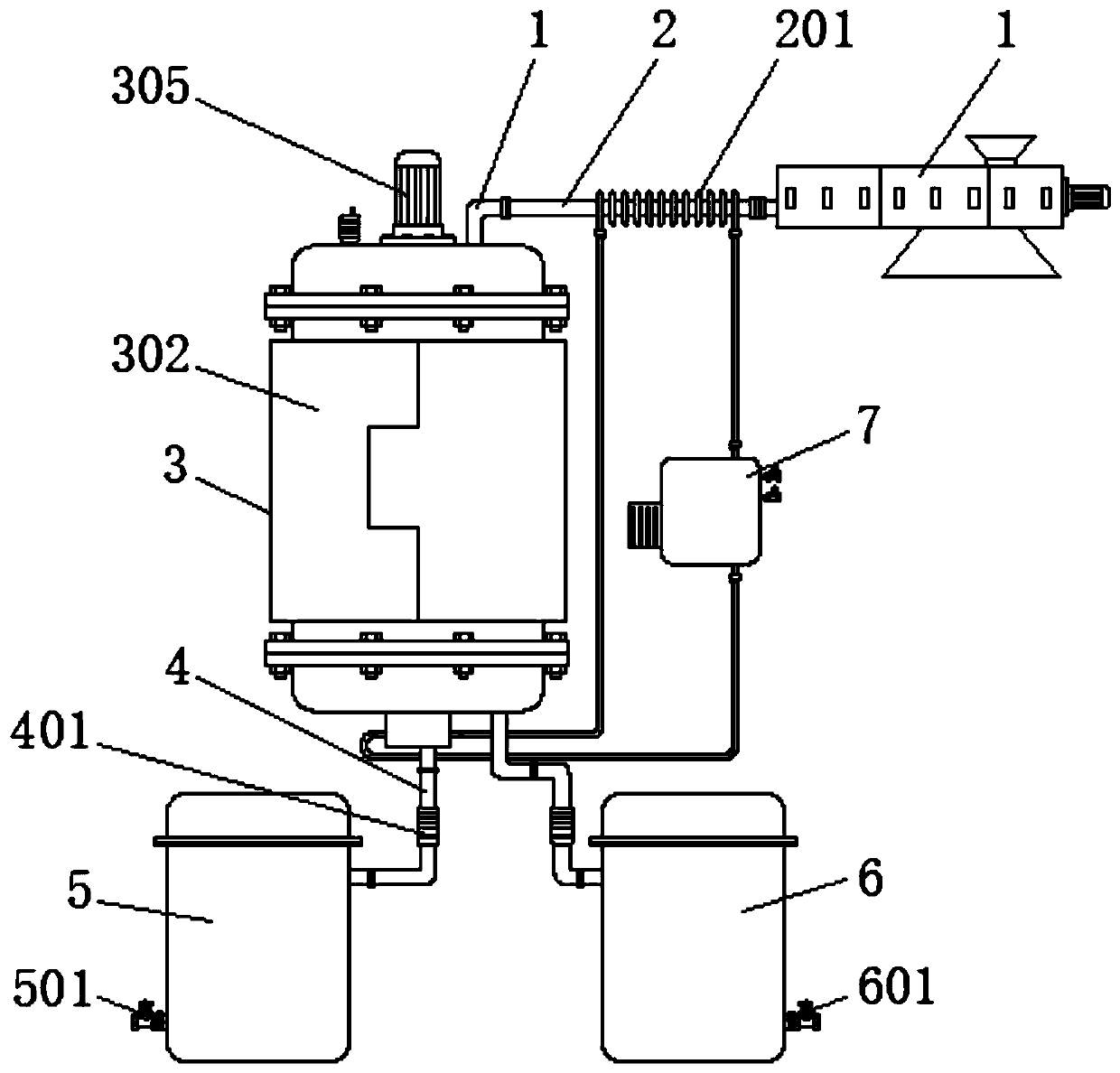
[0024] Such as Figure 1-4 As shown, the present invention provides a technical solution: a molecular distillation system, including a screw extruder 1, a feed pipe 2, a distillation chamber 3, a connecting pipe 4, a light medium storage tank 5, a heavy medium storage tank 6 and heat dissipation Box 7, screw extruder 1 and distillation chamber 3 are connected by feed pipe 2. The outer wall of feed pipe 2 is sleeved with coil 201, distillation chamber 3 includes distillation tank 301, and the outer wall of distillation tank 301 is provided with heating clamps. Cover 302, the top and bottom of the distillation tank 301 are respectively fixed with a top cover 303 and a base 310 by bolts, the top of the top cover 303 is provided with a feed pipe 304, the feed pipe 304 is connected with the feed pipe 2, and the top center of the top cover 303 The motor 305 is fixed by bolts, and the bottom of the motor 305 is connected with a drive shaft 306, the bottom of the drive shaft 306 is sle...


PUM


Abstract

The invention discloses a molecular distillation system, and relates to the technical field of distillation equipment. The system comprises a molecular distillation system, the system comprises a screw extruder, a feeding pipe, a distillation chamber, a connecting pipe, a light medium storage tank, a heavy medium storage tank and a heat dissipation box, wherein the screw extruder is connected withthe distillation chamber through a feeding pipe; the outer wall of the feeding pipe is sleeved with a coil pipe; the distillation chamber comprises a distillation tank; a heating jacket is clamped onthe outer wall of the distillation tank; wherein a top cover and a base are respectively fixed at the top and the bottom of the distillation retort through bolts; and a motor is fixed to the center of the top of the top cover through a bolt. The bottom of the motor is connected with a transmission shaft, the bottom of the transmission shaft is sleeved with a rotary disc, scrapers are fixed to thetwo sides of the bottom of the rotary disc through screws, a vacuum pump is fixed to the top of the top cover through screws, a bottom protrusion is arranged at the bottom of the base, a fixing blockis arranged in the center of the inner wall of the bottom protrusion, and an inverted cone is fixed to the top of the fixing block through the bolts. The distillation system is better in distillationeffect, lower in energy loss and more environment-friendly.

Description

Technical field [0001] The invention relates to the technical field of distillation equipment, in particular to a molecular distillation system. Background technique [0002] Distillation is a thermodynamic separation process. It uses the different boiling points of the components in the mixed liquid system to evaporate the low-boiling components and then condense to separate the entire components. It is a unitary operation of evaporation and condensation. . Compared with other separation methods, such as extraction, adsorption, etc., its advantage is that it does not need to use other solvents other than system components, so as to ensure that no new impurities will be introduced. In some material preparation fields, it is necessary to extract a part of light medium materials from raw materials as production raw materials, such as extracting vitamin E from oils and fats. These extraction processes require molecular stills and molecular distillation systems. [0003] At present,...

Claims


Application Information

Patent Timeline
Patent Type & Authority Applications(China)
IPC IPC(8): B01D3/12
CPCB01D3/12
Inventor 沈洪文
Owner 常熟市新世纪化工设备有限公司
Why Eureka
Try Eureka