Agricultural machinery device for agricultural mulching film covering
A technology of agricultural mulching film and agricultural machinery, which is applied in the field of agricultural mulching film covering agricultural machinery devices, which can solve the problems of inability to adjust, position deviation, inconvenience, etc., achieve convenient disassembly and installation, solve the position limitation, and solve the effect of not falling off
- Summary
- Abstract
- Description
- Claims
- Application Information
AI Technical Summary
Problems solved by technology
Method used
Image
Examples
specific Embodiment approach 1
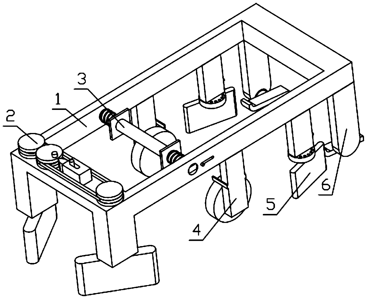
[0040] Combine below Figure 1-14 Describe this embodiment, an agricultural machinery device covered with plastic film, including a mounting frame 1, a soil plowing mechanism 2, a plastic film installation mechanism 3, a crimping wheel 4, a soil covering mechanism 5 and a compaction assembly 6, and the soil plowing mechanism 2 Installed on the installation frame 1, the film installation mechanism 3 is movably installed on the installation frame 1, the edge roller 4 is fixedly installed on the installation frame 1, the soil covering mechanism 5 is fixedly installed on the installation frame 1, and the compaction assembly 6 is fixedly installed on the installation frame 1. On the mounting frame 1, there are two edge rollers 4, soil covering mechanisms 5 and compaction assemblies 6, which are respectively installed on both sides of the mounting frame 1, and the positions are relatively symmetrical;
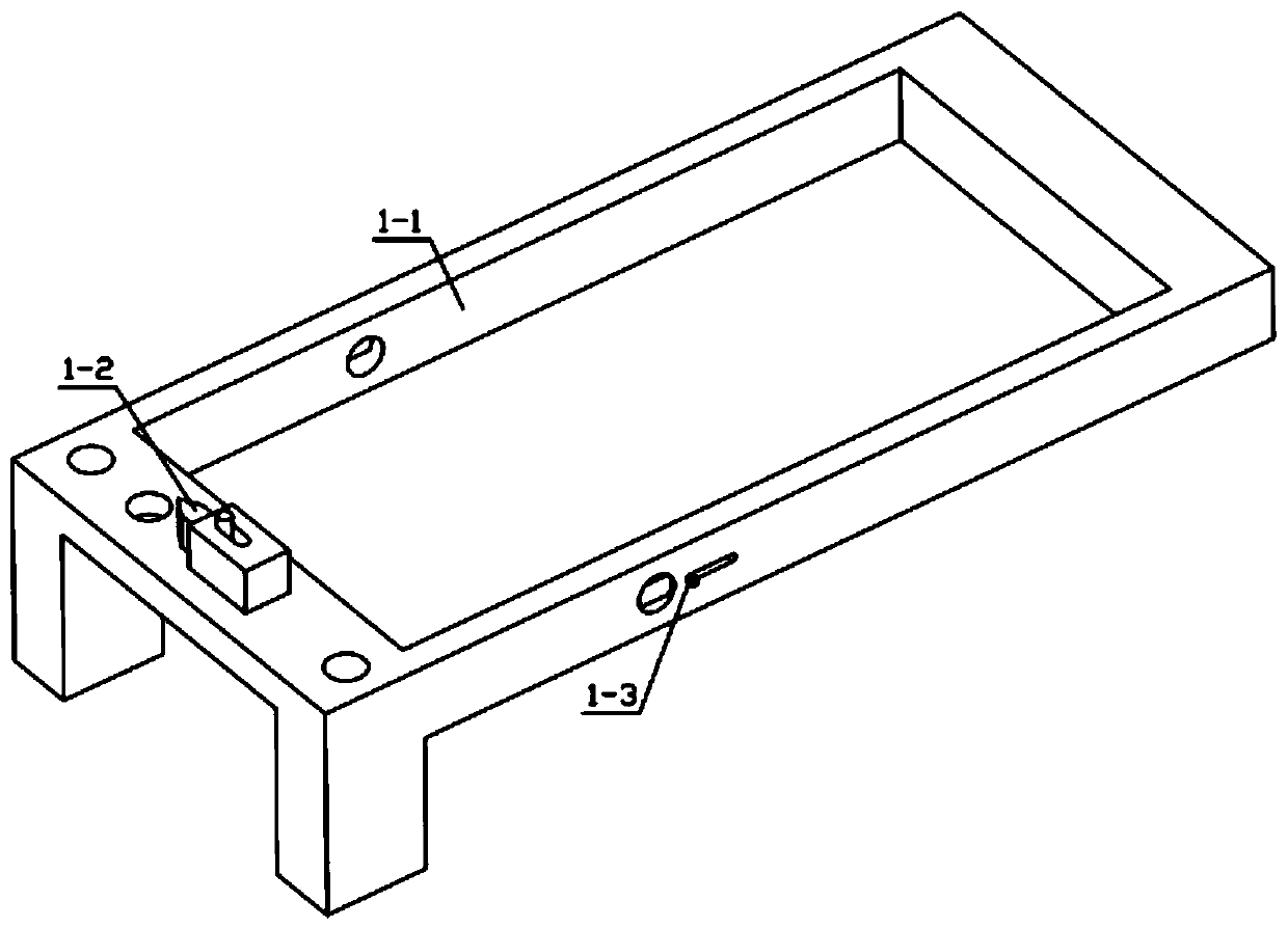
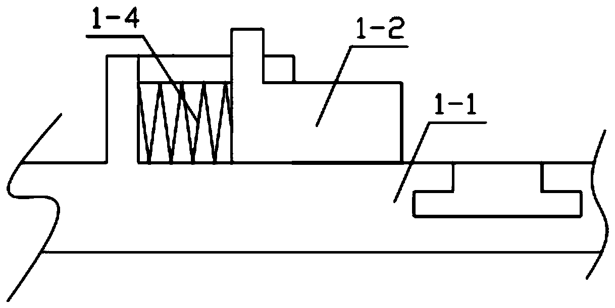
[0041]The mounting frame 1 includes a main frame 1-1, a triangular positioning m...
specific Embodiment approach 2
[0043] Combine below Figure 1-14 Describe this embodiment, this embodiment will further explain the first embodiment, the plow mechanism 2 includes sprocket one 2-1, connecting shaft one 2-2, plow floor one 2-3, sprocket two 2-4 , rotating handle 2-5, chain 2-6, sprocket three 2-7, connecting shaft two 2-8, plow floor two 2-9, connecting shaft one 2-2 is rotatably installed on the main frame 1-1 and arranged On the through-hole, the connecting shaft two 2-8 is rotatably installed on the through-hole provided on the main frame 1-1, the connecting shaft two 2-8 is fixedly connected with the plow floor two 2-9, and the connecting shaft one 2-2 is connected with the plow Floor one 2-3 is fixedly connected, sprocket one 2-1 is fixedly connected with connection shaft one 2-2, sprocket three 2-7 is fixedly connected with connection shaft two 2-8, and sprocket two 2-4 is rotatably installed on the main On the groove provided on the frame 1-1, the first sprocket 2-1 is meshed with th...
specific Embodiment approach 3
[0045] Combine below Figure 1-14 Describe this embodiment. This embodiment will further explain Embodiment 1. The mulch installation mechanism 3 includes a mulch installation rod 3-1, a splint 3-2, a limit spring 3-3, and the mulch installation rod 3-1 is movably installed. On the through hole provided on the main frame 1-1, one end of the limit spring 3-3 is fixedly installed on the main frame 1-1, and the other end of the limit spring 3-3 is fixedly installed on the clamping plate 3-2, and the clamping plate 3-2 is slidingly installed on the mulch installation rod 3-1, and the limit spring 3-3 is set on the mulch installation rod 3-1. There are two splints 3-2 and two limit springs 3-3, respectively It is located at both ends of the film installation rod 3-1, and the positions are symmetrical. The film installation rod 3-1 is in contact with the sealing clip 1-3, and the splints 3-2 on both sides will be closed under the action of the limit spring 3-3. The plastic film is ...
PUM
 Abstract
Description
Claims
Application Information
 - R&D
- Intellectual Property
- Life Sciences
- Materials
- Tech Scout
- Unparalleled Data Quality
- Higher Quality Content
- 60% Fewer Hallucinations
Browse by: Latest US Patents, China's latest patents, Technical Efficacy Thesaurus, Application Domain, Technology Topic, Popular Technical Reports.
© 2025 PatSnap. All rights reserved.Legal|Privacy policy|Modern Slavery Act Transparency Statement|Sitemap|About US| Contact US: help@patsnap.com


