
cable connection assembly

A technology for connecting components and cables, which is applied in the direction of connection, parts of connection devices, fixed/insulated contact components, etc. It can solve the problems of insulation substrate falling off and poor connection reliability, etc., to improve strength, improve reliability, and ensure reliability Effects on sex and stability

Active Publication Date: 2021-07-30
CHINA AVIATION OPTICAL-ELECTRICAL TECH CO LTD
View PDF1 Cites 0 Cited by
  • Summary
  • Abstract
  • Description
  • Claims
  • Application Information

AI Technical Summary

Problems solved by technology

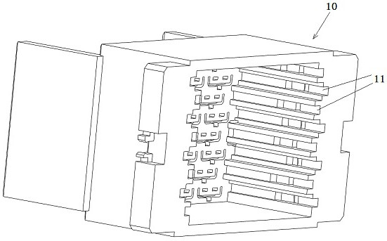
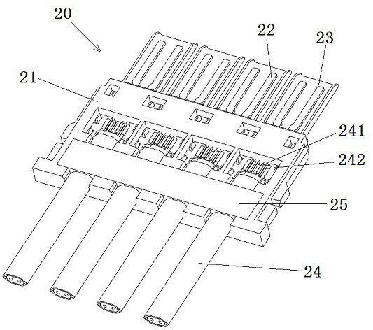
[0005] The purpose of the present invention is to provide a cable connection assembly, which can solve the problem of poor connection reliability caused by the existing cable holders being connected to the insulating substrate only by adhesive force and easily falling off the insulating substrate when subjected to a large external force The problem

Method used


Image

  • cable connection assembly
  • cable connection assembly
  • cable connection assembly

Examples


Embodiment Construction

[0041] In order to make the object, technical solution and advantages of the present invention more clear, the present invention will be further described in detail below in conjunction with the accompanying drawings and embodiments. It should be understood that the specific embodiments described here are only used to explain the present invention, and are not intended to limit the present invention, that is, the described embodiments are only some of the embodiments of the present invention, but not all of the embodiments. The components of the embodiments of the invention generally described and illustrated in the figures herein may be arranged and designed in a variety of different configurations.

[0042] Accordingly, the following detailed description of the embodiments of the invention provided in the accompanying drawings is not intended to limit the scope of the claimed invention, but merely represents selected embodiments of the invention. Based on the embodiments of ...


PUM


Abstract

The invention provides a cable connection assembly, which can solve the problem of poor connection reliability caused by the existing cable holders being connected to an insulating substrate only by adhesive force and easily falling off from the insulating substrate when subjected to a relatively large external force. . The cable connection assembly includes: cable; connector; the connector includes an insulating substrate; the contact assembly is installed on the insulating substrate and connected with the cable core in the cable; the injection molded holding part is used for inserting the cable to make the cable and the insulating substrate The substrate is relatively fixed; the insulating substrate has a molding surface for forming an injection-molded holding part, and an anti-off molding cavity communicated with the molding surface; the anti-off molding cavity includes an overflow channel extending from the molding surface into the insulating substrate, and a flow channel communicating with the overflow channel. The anti-off pouring cavity; and the anti-off pouring cavity has an anti-off cavity wall, and the anti-off cavity wall and the part formed in the anti-off pouring cavity in the injection molding holding part block and cooperate in the thickness direction of the insulating substrate to prevent the injection molding holder from The insulating substrate is peeled off.

Description

technical field [0001] The invention relates to a cable connection assembly. Background technique [0002] The existing cable connection assembly includes an insulating shell, and a plurality of terminal modules are inserted in the insulating shell. The structure of the terminal module is as disclosed in the patent document with the authorized announcement number CN207559189U and the authorized announcement date of 2018.06.29. Similarly, it mainly includes an insulating substrate on which multiple sets of contact assemblies are arranged, and the contact assemblies are further divided into signal contacts and ground contacts for connecting with cables to form a cable connection assembly. The upper surface of the insulating substrate is provided with a concave card slot, which is formed by extending inward from the side of the insulating substrate, and runs through the side wall of the insulating substrate for the cable core to be placed in the corresponding card slot to reali...

Claims


Application Information

Patent Timeline
Patent Type & Authority Patents(China)
IPC IPC(8): H01R13/40H01R13/502
CPCH01R13/40H01R13/502
Inventor 李栋
Owner CHINA AVIATION OPTICAL-ELECTRICAL TECH CO LTD
Learn More