Automatic monitoring device for sewage treatment

An automatic monitoring and monitoring device technology, applied in the direction of clamping/extracting device, program control, computer control, etc., can solve the problems of waste of material and financial resources, weak monitoring and monitoring, time-consuming and labor-intensive labor utilization, etc., to achieve operation Convenience, quick and easy installation and storage, and simple structure

Active Publication Date: 2020-08-07
SHANGHAI WEINENG ENERGY TECH
View PDF5 Cites 3 Cited by
  • Summary
  • Abstract
  • Description
  • Claims
  • Application Information

AI Technical Summary

Problems solved by technology

[0004] The purpose of the present invention is to provide a kind of automatic monitoring and monitoring device for sewage treatment, to solve the traditional sewage treatment proposed in the above-mentioned background technology is to use the reaction tank to carry out filtration reaction to complete decontamination, in the monitoring and monitoring of the reaction treatment tank The degree of regional attention is still relatively weak. The current technology is to use manual inspections at regular intervals to achieve the monitoring and monitoring role in sewage treatment. There are also some sewage treatment areas where large-scale testing instruments are installed near each sewage treatment pool. Due to the large size and time-consuming and laborious installation, it leads to a waste of material and financial resources when installing monitoring and monitoring equipment, which is not conducive to the energy saving of sewage treatment. The purpose of emission reduction, and the equipment does not have variability, and cannot adapt to different environments for monitoring and monitoring, so that the equipment is subject to certain limitations when it is used.

Method used


Image

  • Automatic monitoring device for sewage treatment
  • Automatic monitoring device for sewage treatment
  • Automatic monitoring device for sewage treatment

Examples


Embodiment Construction

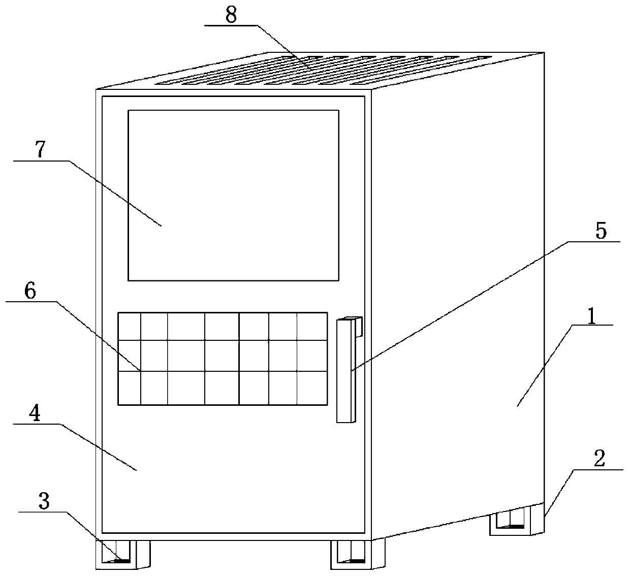
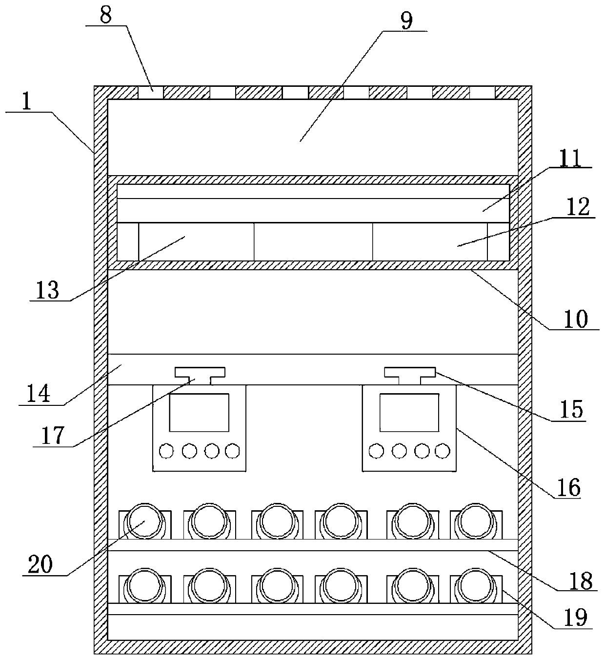
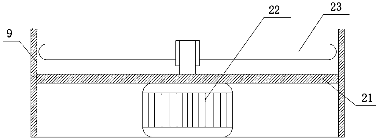
[0028] see Figure 1-2 , in an embodiment of the present invention, an automatic monitoring and monitoring device for sewage treatment, comprising a support box 1, the bottom surface of the support box 1 is fixedly welded with a support bottom block 2, and the bottom surface of the support bottom block 2 is provided with a fixed through hole 3 to support One side opening end hinge of box body 1 is connected with sealing door panel 4, and the side of sealing door panel 4 is provided with lock handle 5, and the number of support bottom blocks 2 is U-shape is four, and support bottom block 2 is buckle The connection shape is arranged on the bottom surface of the supporting box 1 close to the four corners, the sealing door panel 4 is arranged on the inner side of the opening end of the supporting box 1, and one end of the lock handle 5 penetrates the inside of the sealing door panel 4 and is fixedly welded to the supporting lock. 24, the side of the sealing door panel 4 is inlaid ...


PUM


Abstract

The invention discloses an automatic monitoring device for sewage treatment and relates to the field of sewage treatment, the device comprises a supporting box, and is characterized in that a supporting bottom block is fixedly welded on the bottom surface of the supporting box body; a fixed through hole is formed in the bottom surface of the supporting bottom block; a sealing door plate is connected to the opening end of one side of the supporting box body through a hinge, a lock catch handle is arranged on the side edge of the sealing door plate, a setting panel is embedded in the side edge of the sealing door plate, a display screen is embedded in the side edge of the sealing door plate, and air diffusion grids are evenly arranged on the top face of the supporting box body. The device isdesigned into a split structure and is simple in structure and convenient to operate; according to the sewage treatment monitoring device, a plurality of separated designs are adopted, so that the device can be placed and monitored according to specific conditions during use, and is convenient and quick to mount and store, the time of workers is greatly saved, and the sewage treatment monitoringcan be more quickly and efficiently completed.

Description

technical field [0001] The invention relates to the technical field of sewage treatment, in particular to an automatic monitoring and monitoring device for sewage treatment. Background technique [0002] When treating sewage, in order to reduce the amount of sewage discharge and its complexity, it should be combined with the construction of biogas digesters that the country is vigorously promoting to separate the flushing water (black water) and other domestic water (gray water) in domestic water. Gray water is treated with a natural purification system, and black water and human and animal manure are treated with anaerobic digesters, which can not only reduce sewage discharge, complexity and treatment costs, but also contribute to the development of clean new energy in rural areas, the protection of human settlements, and the promotion of rural economies. It is of great significance to the sustainable development of society. Sewage treatment is the process of purifying sew...

Claims


Application Information

Patent Timeline
Patent Type & Authority Applications(China)
IPC IPC(8): G05B19/048G08C17/02H05K5/00H05K5/02H05K7/14
CPCG05B19/048G08C17/02H05K5/0017H05K5/0217H05K7/1411
Inventor 陈婷婷
Owner SHANGHAI WEINENG ENERGY TECH
Why Eureka
Try Eureka