Bearing steel ball test bench

A bearing steel ball and test bench technology, which is used in mechanical bearing testing, testing wear resistance, measuring devices, etc., can solve problems such as inability to determine whether there are defects in bearing materials, uncertainty of rolling element trajectory, and rolling element damage. , to achieve the effect of increasing the number of samples and randomness, requiring less assembly space, and being easy to achieve

Active Publication Date: 2020-08-07
HENAN UNIV OF SCI & TECH +1
View PDF23 Cites 0 Cited by
  • Summary
  • Abstract
  • Description
  • Claims
  • Application Information

AI Technical Summary

Problems solved by technology

[0003] Most of the testing machines used by technicians at this stage are to test and study the entire bearing under different speeds, loads, ambient temperatures or lubrication conditions. Due to the complexity of the force during work and the uncertainty of the trajectory of the rolling elements, it is difficult to determine what caused the damage to the rolling elements, so it is also impossible to determine whether the bearing material itself used to make the rolling elements has defects

Method used


Image

  • Bearing steel ball test bench
  • Bearing steel ball test bench
  • Bearing steel ball test bench

Examples


Embodiment 1

[0051] Embodiment 1 of the bearing steel ball test rig in the present invention: the bearing steel ball test rig in the present invention is used for testing and researching the fatigue life of the bearing steel ball as the rolling element in the bearing, mainly to make the material to be tested into bearing steel The ball simulates the long-term motion of bearing steel balls between the bearing inner ring and bearing outer ring, providing data support for the research of bearing steel balls.

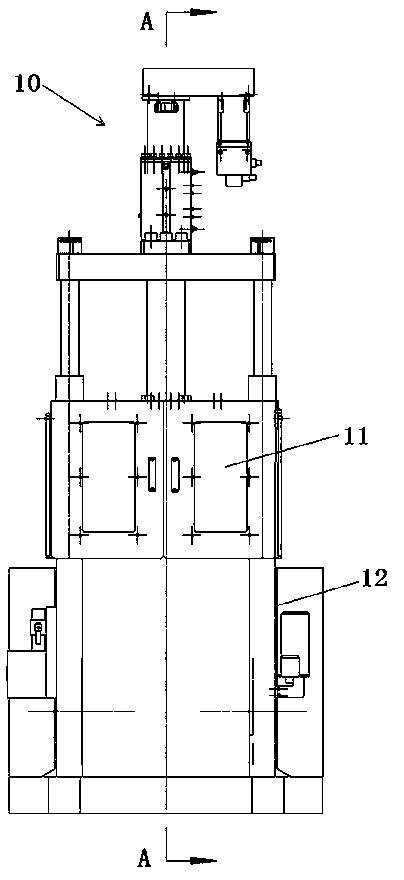
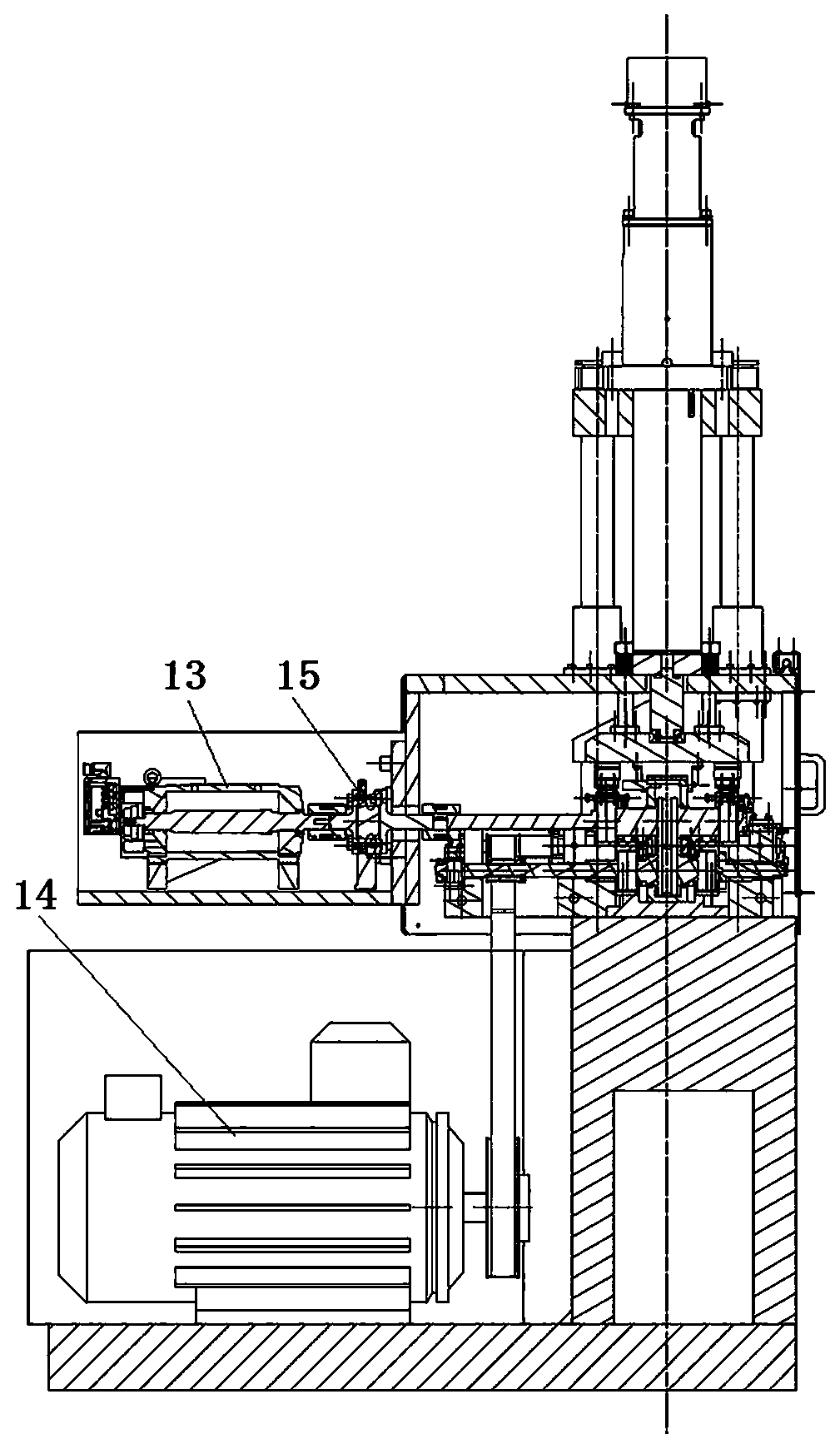
[0052] Such as figure 1 and figure 2 As shown, the bearing steel ball test bench 10 includes a frame 12 on which components for different functions are arranged. The upper part of the frame 12 is arranged with a test chamber 11, in which a friction pair for frictional cooperation with the bearing steel ball to be tested is arranged. Corresponding to the friction wheel on the wheel shaft, the three rotating wheels are further divided into a driving wheel and a driven wheel according t...

Embodiment 2

[0065] Embodiment 2 of the bearing steel ball test bench in the present invention: the difference from the above embodiment is that the frame in this embodiment is provided with a bearing seat for supporting the driving shaft, and the driving shaft is connected to the bearing in the bearing seat through screws. The inner ring is connected, and there are multiple screw holes on the drive shaft for the operator to adjust the installation position of the drive shaft and the bearing. The operator can move the driving wheel in the trial wheel set axially by adjusting the installation position of the driving shaft. In other embodiments, all driving wheels and driven wheels in a test wheel set can adopt the method for adjusting the axial position provided in embodiment 1 and embodiment 2; it can also be only driving wheels or one of the driving wheels and The axial position of a driven wheel is adjustable.

Embodiment 3

[0066] Embodiment 3 of the bearing steel ball test bench in the present invention: the difference from the above embodiment is that the axial position of the driven shaft as the wheel shaft in this embodiment cannot be adjusted, and the operator can use tools to directly adjust the center of the driven wheel. The friction wheel exerts an axial force, so that the friction wheel moves a small distance along the axial direction of the wheel shaft, thereby realizing the adjustment of the axial position of the friction wheel. This solution can also be used to adjust the installation position of the driving wheel and the driving shaft.


PUM


Abstract

The invention provides a bearing steel ball test bench, which can be matched with a bearing steel ball to simulate the movement of the bearing steel ball between an inner ring and an outer ring, and provides a movement model for technicians to research the performance of the bearing steel ball. The test bench comprises a frame; a rotation driving mechanism; a friction pair which comprises at leastthree rotating wheels, wherein each rotating wheel comprises a wheel shaft and a friction wheel arranged on the corresponding wheel shaft in a rotation stopping mode, and the axes of the wheel shaftsof the rotating wheels are parallel. Three of the plurality of rotating wheels are arranged in a manner that respective rotating centers correspond to three vertexes of the triangle to form a test wheel set; the three rotating wheels form a test wheel set; at least one friction wheel is axially and adjustably installed on the corresponding wheel shaft, and/or at least one wheel shaft is axially and adjustably installed on the rack, so the friction wheel on the friction wheel can axially deviate relative to the friction wheels on other rotating wheels, and the contact position of the bearing steel ball to be tested and the rotating wheels is changed.

Description

technical field [0001] The invention relates to a test bench for bearing steel balls. Background technique [0002] Rolling bearings are one of the widely used components in modern machines, which rely on the rolling contact between the main elements to support the rotating parts. Most of the rolling bearings in the prior art have been standardized, mainly including an inner ring, an outer ring, rolling elements and a cage, and the rolling elements correspond to the inner ring and the outer ring to form a friction pair in the rolling bearing. When the rolling element is working, it will slide and roll relative to the inner ring and the outer ring at the same time. The magnitude and direction of the friction force on the rolling element are complex and changeable. In order to ensure the service life and reliability of the rolling element and rolling bearing, technicians will In the research and development stage, the performance of the rolling elements is tested and evaluate...

Claims


Application Information

Patent Timeline
Patent Type & Authority Applications(China)
IPC IPC(8): G01N3/56G01N3/02G01M13/04
CPCG01N3/56G01N3/02G01M13/04
Inventor 刘建杜三明杨勇孟焕玉谷春华张永振
Owner HENAN UNIV OF SCI & TECH
Why Eureka
Try Eureka