
Dehumidification device and air conditioner system

A technology of air conditioning system and dehumidification fan, applied in air conditioning system, space heating and ventilation, heating mode, etc., can solve the problems of complex system and poor dehumidification and regeneration effect of the runner, and achieves simplified device structure, improved operation efficiency, enhanced The effect of heat exchange

Pending Publication Date: 2020-08-07
QINGDAO HAIER AIR CONDITIONER GENERAL CORP LTD +1
View PDF0 Cites 3 Cited by
  • Summary
  • Abstract
  • Description
  • Claims
  • Application Information

AI Technical Summary

Problems solved by technology

[0005] In order to solve at least one of the above-mentioned problems in the prior art, that is, in order to solve the problem of poor dehumidification and regeneration effect of the existing runner and complex system caused by solution dehumidification, the present invention provides a dehumidification device, which includes: a dehumidification box, The dehumidification box is provided with a dehumidification inlet, a dehumidification outlet, a reduction inlet and a reduction outlet, the dehumidification inlet or the dehumidification outlet is provided with a dehumidification fan, and the reduction inlet or the The reduction air outlet is provided with a reduction fan; a solid adsorption assembly, the solid adsorption assembly is fixed in the dehumidification box, and the solid adsorption assembly includes a solid adsorbent; a reduction assembly, the reduction assembly includes a reduction coil, the Part of the reduction coil is arranged on the solid adsorption component, and the heat exchange medium is allowed to flow through the reduction coil

Method used


Image

  • Dehumidification device and air conditioner system
  • Dehumidification device and air conditioner system
  • Dehumidification device and air conditioner system

Examples


Embodiment 1

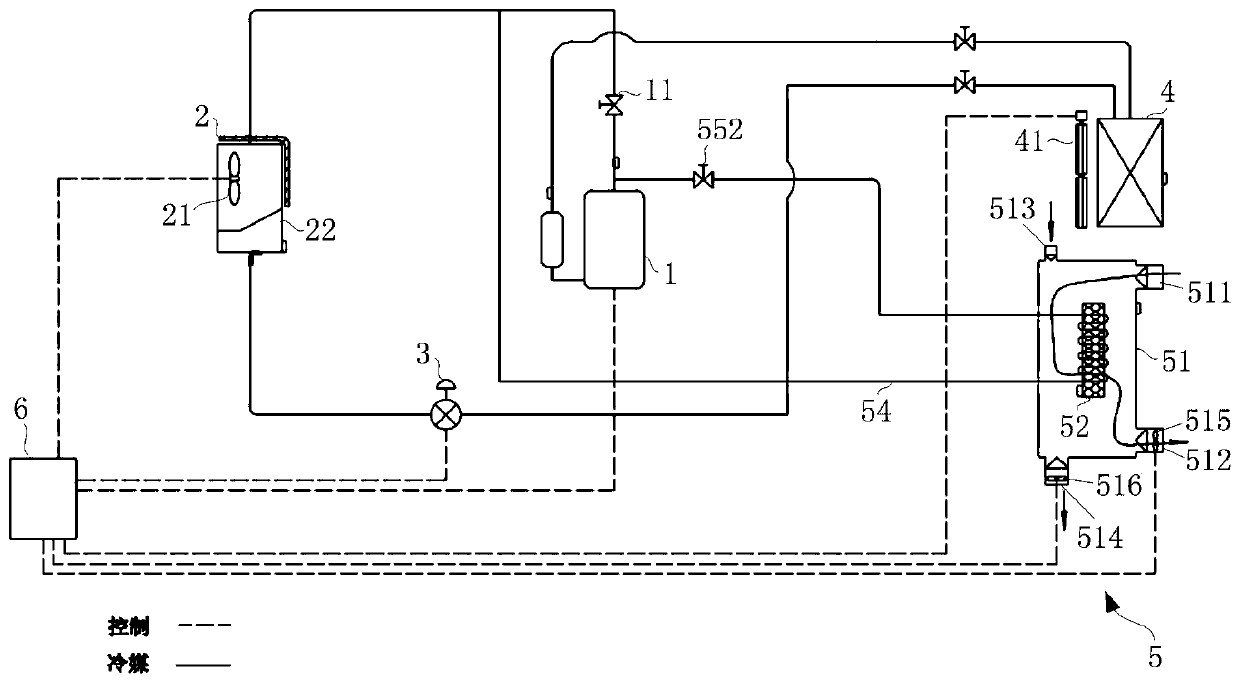
[0034] First refer to figure 1 , the air conditioning system of the present invention will be described. in, figure 1 It is a system diagram of 1st Embodiment of the air conditioning system of this invention.

[0035] like figure 1As shown, in order to solve the problems that the existing runner has poor dehumidification and regeneration effect and the solution dehumidification causes the system to be complicated, the air conditioning system of the present application mainly includes a compressor 1, an outdoor heat exchanger 2, an outdoor fan 21, a second throttling element 3, Indoor heat exchanger 4 , indoor fan 41 and general controller 6 . The compressor 1, the outdoor heat exchanger 2, the outdoor fan 21, the second throttling element 3 and the general controller 6 are arranged in the casing 22 of the outdoor unit, and the indoor heat exchanger 4 and the indoor fan 41 are arranged in the indoor unit. The compressor 1, the outdoor heat exchanger 2, the second throttling...

Embodiment 2

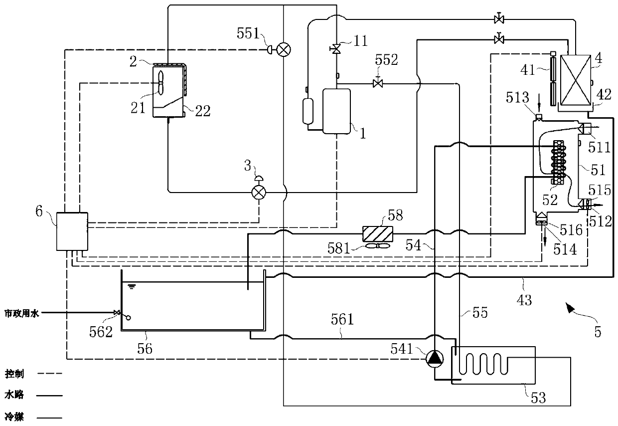
[0043] Refer below figure 2 , a more preferred embodiment of the present application is introduced. in, figure 2 It is a system diagram of 2nd Embodiment of the air conditioning system of this invention.

[0044] like figure 2 As shown, in a preferred embodiment, the air conditioning system mainly includes a compressor 1, an outdoor heat exchanger 2, an outdoor fan 21, a second throttling element 3, an indoor heat exchanger 4, an indoor fan 41, an indoor connection The water pan 42 , the condensate water pipe 43 and the master controller 6 . The compressor 1, the outdoor heat exchanger 2, the outdoor fan 21, the second throttling element 3 and the general controller 6 are arranged in the casing 22 of the outdoor unit, and the indoor heat exchanger 4, the indoor fan 41 and the indoor water receiving tray 42 are arranged In the indoor unit, one end of the condensed water pipe 43 is communicated with the indoor water receiving pan 42, and the other end is led out of the ou...

Embodiment 3

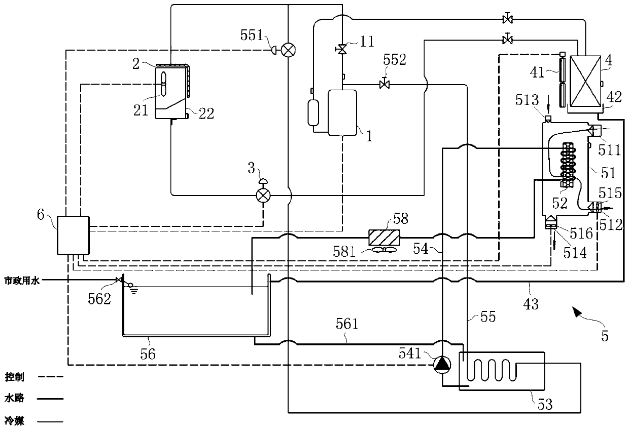
[0068] Combine below image 3 , another alternative embodiment of the present invention is introduced. in, image 3 It is a system diagram of 3rd Embodiment of the air conditioning system of this invention.

[0069] like image 3 As shown, the difference between this embodiment and Embodiment 2 is that the water replenishing port of the cooling water tank 56 is arranged on the side wall away from the bottom of the cooling water tank 56 . This arrangement can ensure the water volume in the cooling water tank 56 during the operation of the air conditioning system, thereby improving the heat exchange effect between the refrigerant and the heat exchange liquid in the reducing water tank 53, improving the efficiency of the air conditioning system, and further reducing energy consumption.


PUM


Abstract

The invention relates to the technical field of air conditioning, in particular to a dehumidification device and an air conditioner system. The dehumidification device and the air conditioner system aim to solve the problems that in the prior art, rotating wheel dehumidification is poor in regeneration effect, and solution dehumidification causes system complexity are solved. The dehumidificationdevice comprises a dehumidification box and a reduction assembly, wherein a solid adsorption assembly is fixedly arranged in the dehumidification box, the reduction assembly comprises a reduction coilpipe, part of the reduction coil pipe is coiled on the solid adsorption assembly, and a heat exchange medium is allowed to flow through the reduction coil pipe. According to the dehumidification device and the air conditioner system, on the premise of ensuring the regeneration effect of a solid adsorbent, the device structure is simplified, and the system complexity is reduced.

Description

technical field [0001] The invention relates to the technical field of air conditioning, in particular to a dehumidification device and an air conditioning system. Background technique [0002] The air-conditioning system with independent temperature and humidity control can control the indoor temperature and indoor humidity separately, thereby avoiding the problems of obvious cooling and poor user experience in the dehumidification process in the existing technical solutions using refrigeration and dehumidification. [0003] In the existing air-conditioning systems with independent temperature and humidity control, the dehumidification methods are mostly realized by rotary dehumidification or solution dehumidification. However, due to the high requirement of the regeneration temperature of the solid adsorbent in rotary dehumidification, the regeneration of the solid adsorbent only by the hot air flow has the problem of poor effect. The solution dehumidification needs to us...

Claims


Application Information

Patent Timeline
IPC IPC(8): F24F1/0083
CPCF24F1/0083
Inventor 罗荣邦王飞董旭许文明张心怡
Owner QINGDAO HAIER AIR CONDITIONER GENERAL CORP LTD
Learn More