
Automatic armrest

A handrail and automatic technology, applied in the direction of handrails, building structures, stepped structures, etc., can solve the problems of handrail adsorption and easy falling off, and achieve the effects of not easy falling off, avoiding air leakage, and ensuring airtightness

Pending Publication Date: 2020-08-07
ZHEJIANG HUALE TECH CO LTD
View PDF1 Cites 2 Cited by
  • Summary
  • Abstract
  • Description
  • Claims
  • Application Information

AI Technical Summary

Problems solved by technology

[0005] The purpose of the present invention is to address the above problems in the prior art, and propose an automatic handrail, which solves the problem that the existing handrail is easy to fall off after adsorption

Method used


Image

  • Automatic armrest
  • Automatic armrest
  • Automatic armrest

Examples


Embodiment 1

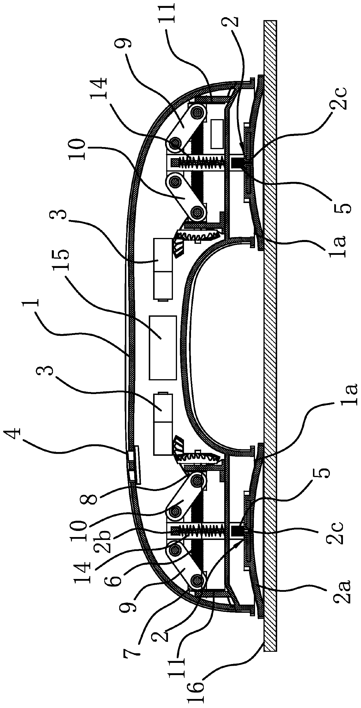
[0030] Such as figure 1 As shown, the automatic handrail includes a U-shaped handle-shaped housing 1, a power supply unit 15, a drive motor 3 and a trigger 4. There is a cavity inside the housing 1, and the drive motor 3 and the power supply unit 15 are fixed in the cavity. The component 4 is connected to the casing 1, and both ends of the casing 1 are provided with circular connecting ports 1a, and the two connecting ports 1a are provided with suction cups 2 and part of the suction cups 2 protrude from the connecting port 1a.

[0031]Wherein, the drive motor 3 is connected to the sucker 2 through the transmission mechanism connected in the casing 1, and the drive motor 3 can drive the sucker 2 to move into the connection port 1a after the trigger 4 is triggered, and make the end faces of the two ends of the casing 1 tighten respectively. Press on the corresponding suction cup 2. In this embodiment, the trigger 4 includes a button; the drive motor 3 is connected to the contro...

Embodiment 2

[0040] The solution of this embodiment is substantially the same as that of Embodiment 1, except that the transmission mechanism includes a screw rod 2 12 rotatably connected in the housing 1 and a nut 3 13 threaded outside the screw rod 12, and the setting of the screw rod 2 12 The direction is consistent with the moving direction of the sucker 2, the driving motor 3 can drive the screw rod 2 12 to rotate circumferentially, and the nut 3 13 is fixed with the rod portion 2b of the sucker 2. When the driving motor 3 works, the gear set drives the screw rod 2 12 to rotate circumferentially. Because the nut 3 13 is fixed to the suction cup 2, the nut 3 13 does not rotate circumferentially, but moves along the axial direction of the screw rod 2 12, and then Drive suction cup 2 to move along the axial direction of screw rod 2 12. The trigger 4 can also include a position sensor fixed on the housing 1, which can be used to detect whether the user's hand is blocked, and can also be u...


PUM


Abstract

The invention provides an automatic armrest, and belongs to the technical field of daily living equipment. The problem that an existing armrest is likely to fall off after being adsorbed is solved. The automatic armrest comprises a handle-shaped shell, and connecting openings are formed in the two ends of the shell. Suction cups are arranged on the two connecting openings, and the suction cups partially stretch out of the connecting openings. The automatic armrest further comprises a driving motor and a trigger, and the driving motor is connected in the shell and connected with the suction cups through a transmission mechanism. The driving motor drives the suction cups to move into the connecting openings after the trigger is triggered, and the end faces of the two ends of the shell are compressed on the corresponding suction cups correspondingly. The automatic armrest has advantage of being good in adsorption stability.

Description

technical field [0001] The invention belongs to the technical field of daily necessities, and relates to an automatic handrail, in particular to a portable automatic handrail that can be fixed automatically. Background technique [0002] At present, all kinds of handrails on the market are firmly fixed on the wall or floor or other places that can be fixed by screw fixing. When these fixed handrails are fixed, they often destroy the wall. After fixing, they should not be moved. more inconvenient. [0003] For this reason, people have designed a kind of portable armrest and have applied for Chinese patent (its application number is: 201920670661.3; Its announcement number is: CN209904601U), this portable type armrest comprises outer casing, and the middle part of outer casing is hand-held part, and outer casing There are circular enlarged parts at both ends, the upper end of the circular enlarged part is equipped with a flip button, the bottom of the circular enlarged part i...

Claims


Application Information

Patent Timeline
Patent Type & Authority Applications(China)
IPC IPC(8): E04F11/18
CPCE04F11/18E04F11/1802
Inventor 林泓鑫
Owner ZHEJIANG HUALE TECH CO LTD
Learn More