Financial voucher arranging and binding device

A voucher and financial technology, applied in the field of financial voucher sorting and binding devices, can solve the problems of voucher dislocation, unguaranteed binding quality, troublesome operation, etc., and achieve the effect of ensuring binding effect, realizing automatic operation, and improving work efficiency.

Inactive Publication Date: 2020-08-07
SUIHUA UNIV
View PDF5 Cites 3 Cited by
  • Summary
  • Abstract
  • Description
  • Claims
  • Application Information

AI Technical Summary

Problems solved by technology

[0003] In the process of using the existing technology, firstly, the sorted vouchers are clamped with clips, and then the punching position is moved to the bottom of the punching mechanism to punch holes. After the punching is completed, the vouchers are sent to the sol mechanism for sol binding. ; This operation is cumbersome, and the voucher needs to be moved back and forth. During the moving process, the voucher will be misplaced, and the binding quality cannot be guaranteed. Therefore, it is necessary to design a financial voucher sorting and binding device to solve the above technical problems

Method used


Image

  • Financial voucher arranging and binding device
  • Financial voucher arranging and binding device
  • Financial voucher arranging and binding device

Examples


Embodiment 1

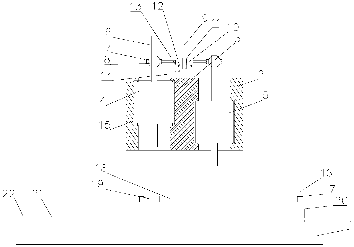
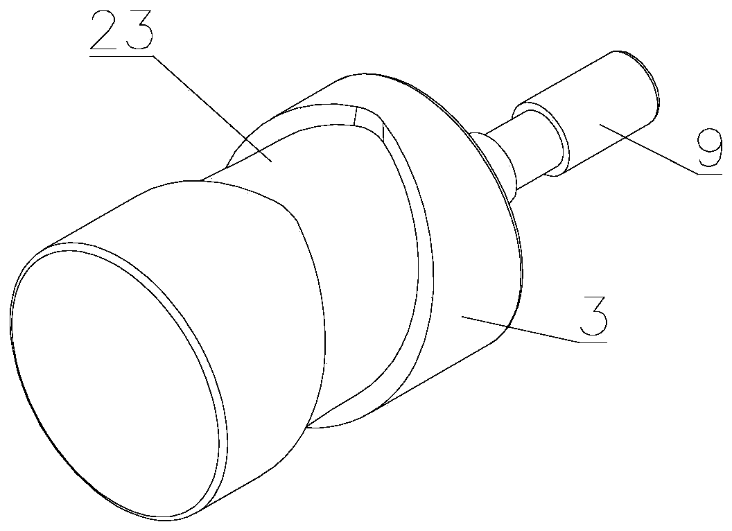
[0028] see Figure 1~4 , in Embodiment 1 of the present invention, a financial voucher sorting and binding device includes a base 1 and a cylinder 2 fixedly installed on the base 1, the inside of the cylinder 2 is fixedly provided with an intermediate shaft 3, and the outer side of the intermediate shaft 3 and The inside of the cylinder 2 is respectively provided with a B slideway 23 and an A slideway 15, and the two ends of the drilling assembly 4 and the hot-melt binding assembly 5 are respectively slidably installed on the B slideway 23 and the A slideway 15, and the B slideway 23 and A slideway 15 are provided with a high position and a low position, and the intermediate shaft 3 is provided with a device to drive the hot-melt binding assembly 5 and the drilling assembly 4 to rotate, so that the hot-melt binding assembly 5 and the drilling assembly 4 are between the high and low positions Change the position, when the drilling assembly 4 is at a low position, the voucher pl...

Embodiment 2

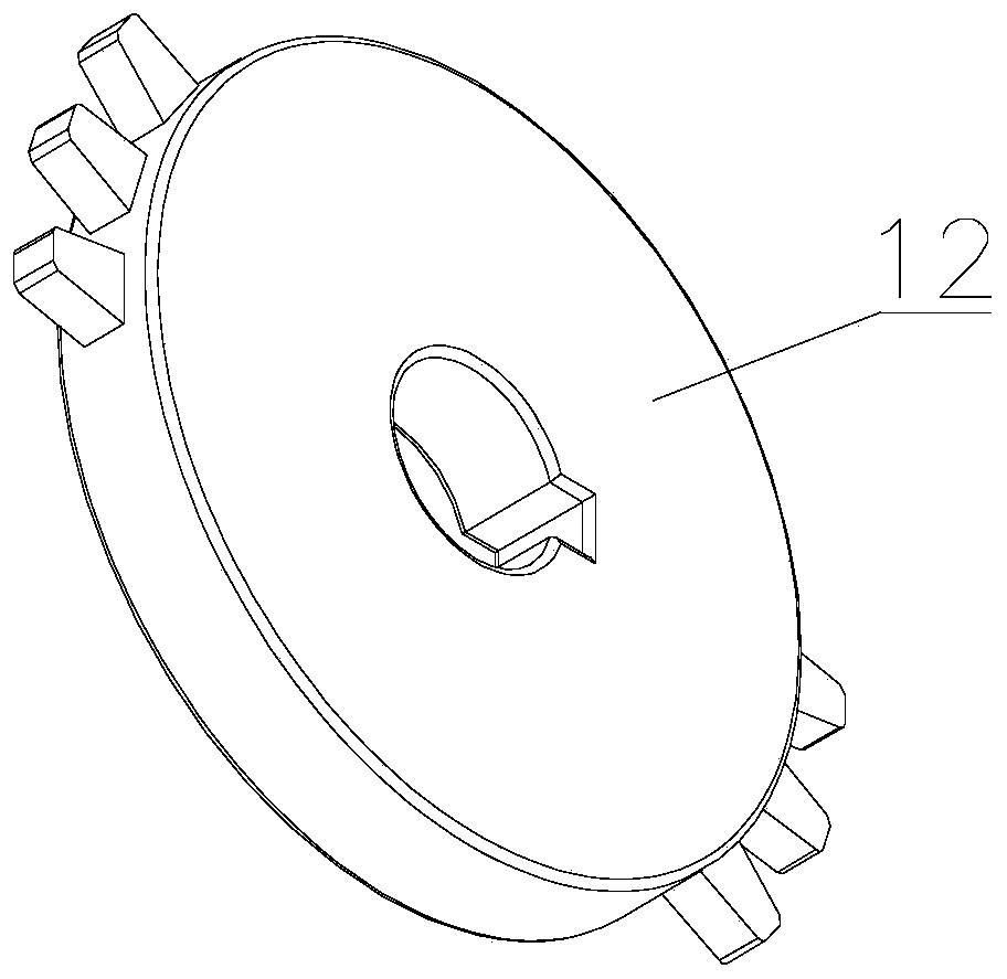
[0030] see Figure 1~4 The main difference between this embodiment 2 and embodiment 1 is that the intermittent drive mechanism includes an incomplete full gear 12 fixedly sleeved on the outside of the sleeve 11 and a disc wheel 13 cooperating with the incomplete full gear 12. Both sides of the complete full gear 12 are respectively provided with meshing tooth sets, and the disc wheel 13 is provided with a mating tooth set that intermittently meshes with the meshing teeth on the incomplete full gear 12, because the mating teeth only engage with one side every time they rotate. The meshing tooth set is meshed, and then the hot-melt binding assembly 5 and the drilling assembly 4 are rotated 180° respectively;

[0031] The disc wheel 13 is disc-shaped, and the upper edge of the convex edge of the disc wheel 13 is set in conjunction with the tooth set.

[0032] The angle difference between the high position and the low position of both the A slideway 15 and the B slideway 23 is 18...


PUM


Abstract

The invention discloses a financial voucher arranging and binding device and relates to the technical field of finance equipment. The financial voucher arranging and binding device comprises a base and a cylinder fixedly installed on the base. The cylinder is internally and fixedly provided with a middle shaft. The outer side of the middle shaft and the inner side of the cylinder are provided witha sliding way A and a sliding way B respectively. The two ends of a drilling assembly and the two ends of a hot melting binding assembly are installed on the sliding way B and the sliding way B in asliding manner respectively. The middle shaft is provided with a drive piece for driving the hot melting binding assembly and the drilling assembly to rotate. The middle shaft is fixedly installed onthe cylinder through a supporting connection rod. The outer side of the supporting connection rod is rotationally sleeved with a sleeve. The two sides of the sleeve are fixedly provided with connection pieces. The end portions, far away from the sleeve, of the connection pieces on the two sides are internally provided with driving rods in an up-down sliding manner. The driving rods on the two sides are fixedly installed on the drilling assembly and the hot melting binding assembly. The sleeve is further provided with an interval drive mechanism. By means of the financial voucher arranging andbinding device, drilling and binding can be completed at a time, the working efficiency is improved, meanwhile automatic running is achieved, and the labor intensity is reduced.

Description

technical field [0001] The invention relates to the technical field of financial equipment, in particular to a sorting and binding device for financial vouchers. Background technique [0002] During financial work, it is necessary to sort out a large number of vouchers and documents from time to time, and the vouchers need to be sorted and then bound. Existing comparatively commonly used voucher binding machine generally comprises a workbench, and a punching mechanism and a sol mechanism are installed side by side on the workbench side, and the punching mechanism and the sol mechanism are all fixed on the installation platform on the workbench side, punching The hole mechanism is used for punching holes, and the sol mechanism is used for fixing the sol after punching. [0003] In the process of using the existing technology, firstly, the sorted vouchers are clamped with clips, and then the punching position is moved to the bottom of the punching mechanism to punch holes. Af...

Claims


Application Information

Patent Timeline
Patent Type & Authority Applications(China)
IPC IPC(8): B42B5/00B42B5/02B42B9/00B26F1/16B26D7/01
CPCB26D7/015B26F1/16B42B5/00B42B5/02B42B9/00
Inventor 张战友唐雪薇王小方
Owner SUIHUA UNIV
Why Eureka
Try Eureka