Speed reducer for two-stroke aviation piston engine used for small and medium-sized UAV

A piston engine and unmanned aerial vehicle technology, applied in the direction of machines/engines, mechanical equipment, transmissions, etc., can solve the problems of accelerating the wear of internal parts of the engine, reducing the reliability and comfort of the engine, and lacking a specific description of the structure of the reducer. , to achieve the effect of reducing vibration and noise, easy disassembly and maintenance, and light weight

Pending Publication Date: 2020-08-04
XIAN AISHENG TECH GRP
View PDF2 Cites 0 Cited by
  • Summary
  • Abstract
  • Description
  • Claims
  • Application Information

AI Technical Summary

Problems solved by technology

[0006] The above-mentioned first patent is to directly install a high-speed propeller at the propeller mounting flange at the front end of the crankshaft. The structure does not install a reducer, but the engine crankshaft directly installs the propeller for power output. For a two-stroke four-cylinder piston engine, the speed is between Above 5000 rpm is a high speed. After the crankshaft is directly installed with the propeller, the high speed will cause the vibration and noise of the engine to be large, accelerate the wear of the internal parts of the engine, and reduce the reliability and comfort of the engine. When the engine is running When operating at high altitude and high speed, due to the decrease of air density, too high speed will also reduce the efficiency of the propeller
The speed reducer proposed in the above-mentioned second patent is a planetary gear speed reducer, and its type is essentially a planetary gear train. The structure of the planetary gear train is relatively complicated. Due to the structure and weight requirements of the drone, its use is limited, and The patent only describes the structure of the gear shaft, and lacks a specific description of the structure of the reducer

Method used


Image

  • Speed reducer for two-stroke aviation piston engine used for small and medium-sized UAV
  • Speed reducer for two-stroke aviation piston engine used for small and medium-sized UAV
  • Speed reducer for two-stroke aviation piston engine used for small and medium-sized UAV

Examples


Embodiment Construction

[0030] The embodiments described below by referring to the figures are exemplary and are intended to explain the present invention and should not be construed as limiting the present invention.

[0031] In describing the present invention, it should be understood that the terms "center", "longitudinal", "transverse", "length", "width", "thickness", "upper", "lower", "front", " Orientation indicated by rear, left, right, vertical, horizontal, top, bottom, inside, outside, clockwise, counterclockwise, etc. The positional relationship is based on the orientation or positional relationship shown in the drawings, which is only for the convenience of describing the present invention and simplifying the description, rather than indicating or implying that the referred device or element must have a specific orientation, be constructed and operated in a specific orientation, Therefore, it should not be construed as limiting the invention.

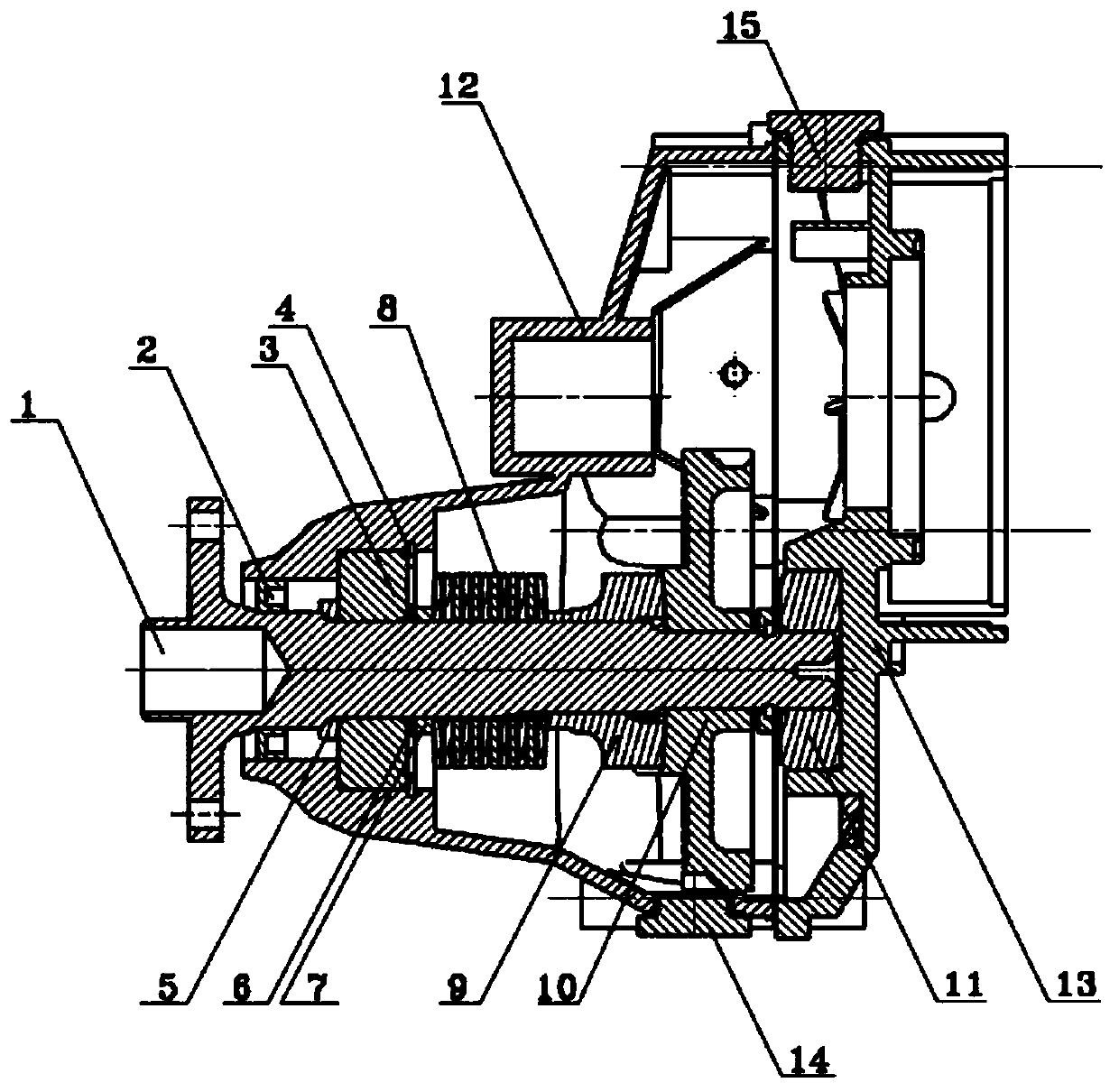
[0032] Such as figure 1 Shown, the speed re...


PUM

PropertyMeasurementUnit
Thicknessaaaaaaaaaa

Abstract

The invention discloses a speed reducer for a two-stroke aviation piston engine used for a small and medium-sized UAV, and belongs to the field of UAV engines. The speed reducer comprises a speed reducer shell with two open ends, the speed reducer shell is composed of a front shell and a rear shell, and the speed reducer further comprises a power output shaft, an oil seal, a belleville spring group, a coupling and a big gear; one end of the power output shaft is mounted in the front shell through a front bearing, the end head of one end of the power output shaft extends out of the end port ofthe front shell, a flange plate for mounting a propeller is arranged on the end head, and the other end of the power output shaft is mounted in the rear shell through a rear bearing; and the belleville spring group, the coupling and the big gear are sequentially mounted between the front bearing and the rear bearing on the power output shaft coaxially. The speed reducer adopts two-stage transmission, the high transmission efficiency is achieved, the small number of parts is achieved, the reliability is high, the overall structure is compact, the light weight is achieved, the overall structureof an original engine does not need to change, while the front-end structure of an engine crankshaft only needs to change, a mounting structure of the speed reducer, the gear and a spline structure are additionally arranged on the speed reducer, and mounting using can be achieved accordingly.

Description

technical field [0001] The invention belongs to the field of drone engines, and in particular relates to a reducer for a two-stroke aviation piston engine used for small and medium-sized drones. Background technique [0002] The engine is the heart of the drone and is used to provide power to the drone. The two-stroke piston engine is widely used as a power output on small and medium-sized drones due to its simple structure, light weight, high power-to-weight ratio, and low manufacturing cost. , It is more and more widely used in military, exploration, monitoring, inspection and other fields. [0003] In the existing power output technology, the small and medium-sized two-stroke aviation piston engines generally use the front end of the crankshaft to directly connect the propeller for power output. The propeller rotates at a high speed, and the vibration and noise are relatively large. [0004] The Chinese patent with the notification number CN108661793A announced "a small ...

Claims


Application Information

Patent Timeline
IPC IPC(8): F16H1/22F16H57/023F16H57/027F16H57/028F16H57/04F02B61/04
CPCF02B61/04F16H1/22F16H57/023F16H57/027F16H57/028F16H57/0402
Inventor 侯磊方宇
Owner XIAN AISHENG TECH GRP
Why Eureka
Try Eureka