Wire clamping spring structure and switch structure

A wire clamping and clamping lug technology, which is applied in the direction of electric switches, contacts, electrical components, etc., can solve the problems of poor contact of switch control lines, variable installation of clamping spring structure, and inability to energize, so as to avoid poor contact or failure The effect of power on, not easy to loosen the wire, and not easy to misalign the wire

Pending Publication Date: 2020-07-31
GREE ELECTRIC APPLIANCES ZHONGSHAN SMALL HOUSEHOLD APPLIANCES MFG +1
View PDF0 Cites 0 Cited by
  • Summary
  • Abstract
  • Description
  • Claims
  • Application Information

AI Technical Summary

Problems solved by technology

[0004] Therefore, the technical problem to be solved by the present invention is to overcome the easy-to-change installation of the clip spring structure in the mechanical plug-in switch in the prior art, so that the plug-in wire is loose and the plug-in line is offset, which leads to poor contact or failure of the switch control circuit. , so as to provide a clamp spring structure and switch structure

Method used


Image

  • Wire clamping spring structure and switch structure
  • Wire clamping spring structure and switch structure
  • Wire clamping spring structure and switch structure

Examples


Embodiment 1

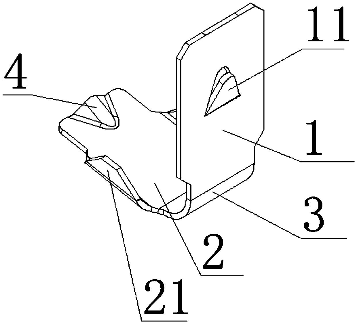
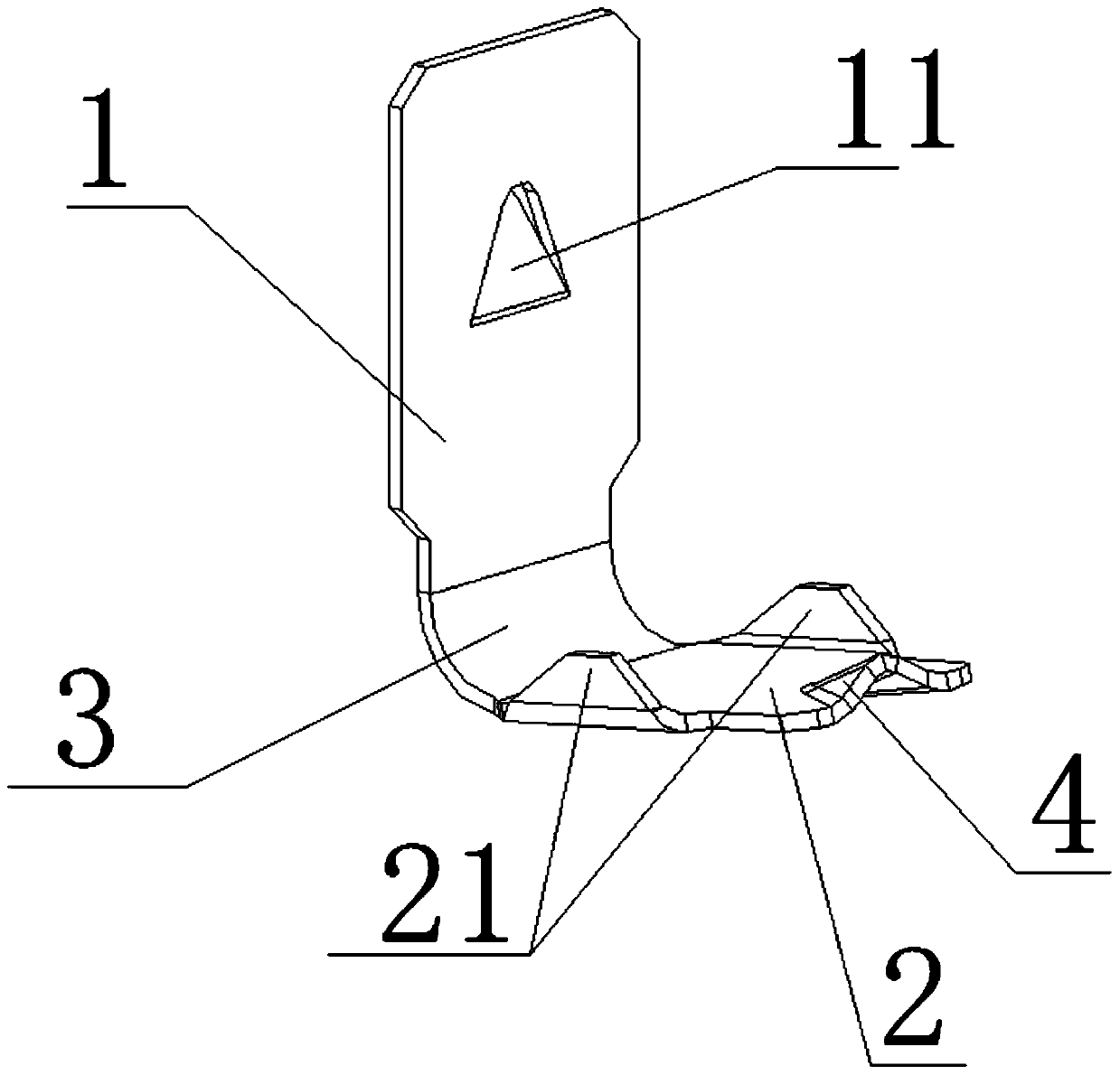
[0043] Such as figure 1 - Figure 4 , In this embodiment, a clamp spring structure is provided, including: a longitudinal arm 1 and a transverse arm 2 .

[0044] The longitudinal arm 1 and the cross arm 2 are connected to form a "V"-shaped bend. The connecting part of the two is the connecting part 3. The connecting part is arranged in an arc shape to avoid scratching the user and disperse the load to improve the strength of the parts. The "V"-shaped bend The inner side of the longitudinal arm 1 and the inner side of the cross arm 2 are oppositely arranged in the bend.

[0045] Wherein the longitudinal arm 1 is arranged in a square sheet shape, and the middle part is provided with a lug part 11, and the lug part 11 protrudes away from the inner surface of the longitudinal arm 1,

[0046]The cross arm 2 is arranged in a sheet shape, and the end portion facing away from the connecting portion 3 is provided with a guide slot 4 protruding along the inner surface of the cross arm...

Embodiment 2

[0066] This embodiment is based on the above-mentioned embodiment 1, such as Figure 5 - Figure 6 As shown, a switch structure is provided in this embodiment, including the above-mentioned clamping spring structure. The switch structure includes a seat body 5, the seat body 5 is fixed with the clamping spring structure, the clamping spring is arranged in the insertion port of the seat body, the tab part 11 on the longitudinal arm 1 is in contact with the inner side wall of the seat body, and the cross arm 2 The end portion of the seat abuts against the inner wall on the other side of the seat body, and a conductive sheet is arranged on the inner wall here. In this way, through the setting of the lug part 11, the phenomena such as loose wire insertion and offset wire insertion that may occur inside the switch are avoided, and problems such as poor contact or inability to power on the whole machine are avoided.


PUM


Abstract

The invention provides a wire clamping spring structure and a switch structure. The structure comprises: a longitudinal arm which is in a sheet shape, and a transverse arm which is sheet-shaped and isconnected with the longitudinal arm to form a V-shaped bend; a connecting part is arranged to be arc-shaped, a guide clamping groove is formed in the end part, extending back to the connecting part,of the cross arm; and a longitudinal arm inner side face and a transverse arm inner side face are oppositely arranged in the V-shaped bend, an edge folding part is arranged on the transverse arm innerside face in a protruding mode, the edge folding part is arranged along the edges of the two sides of the extending direction of the transverse arm, and / or a clamping lug part is arranged on the longitudinal arm inner side face, and the clamping lug part is arranged back to the longitudinal arm inner side face in a protruding mode. Through the arrangement, the structural strength and the installation stability of the wire clamping spring are improved, after the wire clamping spring is installed and matched, the phenomena of plug wire loosening and plug wire deviation are not likely to happen,and the problem that a switch control circuit is poor in contact or cannot be powered on is avoided.

Description

technical field [0001] The invention relates to the technical field of mechanical switches, in particular to a clamp spring structure and a switch structure. Background technique [0002] At present, mechanical plug-in switches are widely used in the market, including rotary switches and key switches. [0003] The clamping spring used in the above switches is in the shape of a "V" sheet. When the clamping spring is assembled at the wire insertion port during use, when the insertion force is slightly strong or forced to be inserted, the wire will be stuck due to improper fit. In addition, there is a problem of stress and deformation of the cable spring at the insertion port of different specifications of wire diameters. When the cable spring is deformed, there may be loose insertion and deviation of the insertion wire inside the switch, which will lead to the whole The problem of poor contact or power failure of the machine. Contents of the invention [0004] Therefore, t...

Claims


Application Information

Patent Timeline
Patent Type & Authority Applications(China)
IPC IPC(8): H01H1/58
CPCH01H1/5844
Inventor 范书洁罗颖何兵曾裕焯
Owner GREE ELECTRIC APPLIANCES ZHONGSHAN SMALL HOUSEHOLD APPLIANCES MFG
Why Eureka
Try Eureka