Construction machinery lubricant filling machine

A technology of construction machinery and lubricants, which is applied in the direction of engine lubrication, mechanical equipment, and lubricating parts, etc. It can solve the problems of enhanced fluidity, reduced mechanical lubrication effect, and poor temperature emission effect of filling machines.

Inactive Publication Date: 2020-07-31
施胜生
View PDF0 Cites 0 Cited by
  • Summary
  • Abstract
  • Description
  • Claims
  • Application Information

AI Technical Summary

Problems solved by technology

[0002] The lubricating oil filling machine is a device that uses a manual piston to drive the plunger to reciprocate to output lubricating oil. Since the filling machine needs to perform piston movement on the lubricating oil inside, the inside of the filling machine must be in a sealed state. State work will increase the internal temperature. When the filling machine works in high temperature weather in summer, due to the small temperature difference between the inside and outside of the filling machine, the temperature discharge effect inside the filling machine is poor. In this case of high temperature sealing The lubricating oil will become thinner. After the lubricating oil becomes thinner, the viscosity will decrease and the fluidity will increase, which will reduce the effect of the lubricating oil on the construction machinery and reduce the lubricating effect of the machinery.

Method used


Image

  • Construction machinery lubricant filling machine
  • Construction machinery lubricant filling machine
  • Construction machinery lubricant filling machine

Examples


Embodiment 1

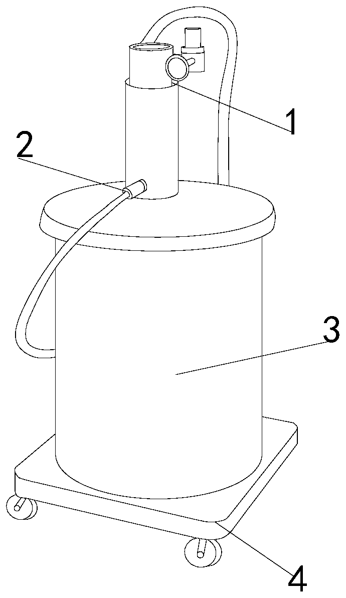
[0025] like Figure 1-Figure 5 Shown:

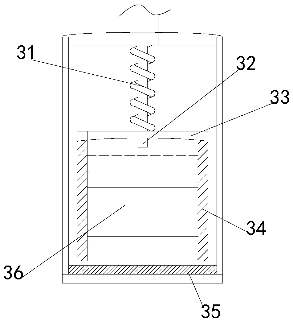
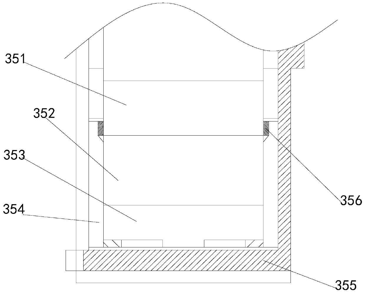
[0026] The present invention is a lubricant filling machine for construction machinery. Its structure includes a hydraulic pump 1, a spray pipe 2, a storage tank 3, and a moving plate 4. The spray pipe 2 is embedded and installed on the side of the hydraulic pump 1. The pump 1 is welded on the upper end of the storage tank 3, the moving plate 4 is fixedly installed on the lower end of the storage tank 3, the center point of the hydraulic pump 1 and the storage tank 3 is located on the same axis, and the storage tank 3 It is composed of an elastic rod 31, an absorber 32, a compression plate 33, a storage box 34, a cooling mechanism 35, and a storage box 36. The absorber 32 and the elastic rod 31 are integrally formed, and the compression plate 33 and the absorber 32 The storage box 36 and the placement box 34 are integrated structures, the cooling mechanism 35 is attached to the lower end of the placement box 34, the compression plate 33...

Embodiment 2

[0033] like Figure 6-Figure 8 Shown:

[0034] Wherein, the absorber 32 is provided with a pressure mechanism c1, a fixed rod c2, and an isolation rod c3, the pressure mechanism c1 and the fixed rod c2 are connected, the fixed rod c2 is welded on the inner wall of the isolation rod c3, and the isolation rod c3 Located on the same center line as the elastic rod 31, the pressure mechanism c1 is provided with a ring structure and a cylindrical structure, the fixed rod c2 runs through the center of the two structures, and the barrier acts on the inner cylinder structure of the pressure mechanism c1, so that the barrier It enters the injection pipe 2 through the pressure mechanism c1.

[0035] Wherein, the pressure mechanism c1 is provided with an engaging mechanism c11, an absorbing rod c12, a sealing plate c13, a rubber block c14, a compression block c15, and a compression column c16, and the sealing plate c13 and the engaging mechanism c11 is an integrated structure, the rubbe...


PUM


Abstract

The invention discloses a construction machinery lubricant filling machine with the structure comprising a hydraulic pump, a spray tube, a holding tank and a moving plate, wherein the spray tube is embedded and installed on the side of the hydraulic pump, the hydraulic pump is welded on the upper end of the holding tank, and the holding tank is composed of an elastic rod, an absorber, a compression plate, a placing box, a cooling mechanism and a holding box. The inside of a solid-liquid mixing tank reaches the temperature equilibrium point under the alternation of cooling and high temperature,so that the viscosity of the lubricating oil in the solid-liquid mixing tank is suitable. The pressure of the lubricating oil with suitable viscosity is sufficient to form pressure on a pressure mechanism, and then the force acts on the internal bearing block of a clamping mechanism, so that a squeezing block compresses a moving block and drives a closing block to move, so as to achieve the effect of lubricating oil passing through an absorption port. The liquid lubricating oil with strong fluidity cannot form a large pressure on the bearing block, thereby preventing the fluid with strong fluidity from lubricating the construction machinery and avoiding poor lubrication effect of the construction machinery.

Description

technical field [0001] The invention relates to the field of construction, in particular to a lubricant filling machine for construction machinery. Background technique [0002] The lubricating oil filling machine is a device that uses a manual piston to drive the plunger to reciprocate to output lubricating oil. Since the filling machine needs to perform piston movement on the lubricating oil inside, the inside of the filling machine must be in a sealed state. State work will increase the internal temperature. When the filling machine works in high temperature weather in summer, due to the small temperature difference between the inside and outside of the filling machine, the temperature discharge effect inside the filling machine is poor. In this case of high temperature sealing The lubricating oil will become thinner. After the lubricating oil becomes thinner, its viscosity will decrease and its fluidity will increase, which will reduce the effect of the lubricating oil o...

Claims


Application Information

Patent Timeline
Patent Type & Authority Applications(China)
IPC IPC(8): F16N37/00F16N39/02
CPCF16N37/00F16N39/02F16N2037/006
Inventor 施胜生
Owner 施胜生
Why Eureka
Try Eureka