
A low-consumption car air filter

An air filter, low-consumption technology, applied in fuel air filter, combustion air/combustion-air treatment, machine/engine, etc., can solve the problems of reduced filter performance, affecting engine work, increasing vehicle maintenance costs, etc. , to achieve the effect of reducing replacement frequency, improving filtration performance and reducing maintenance costs

Active Publication Date: 2022-03-11
浙江益新机械股份有限公司
View PDF19 Cites 0 Cited by
  • Summary
  • Abstract
  • Description
  • Claims
  • Application Information

AI Technical Summary

Problems solved by technology

[0003] Among them, for the air filter on the car, after using it for a period of time, after a large amount of dust and other particles are adsorbed on the filter element in the air filter, its filtering performance will be greatly reduced, which will eventually affect the work of the engine. The filter element in the car air filter is often replaced frequently, which increases the maintenance cost of the car

Method used


Image

  • A low-consumption car air filter
  • A low-consumption car air filter
  • A low-consumption car air filter

Examples


Embodiment 1

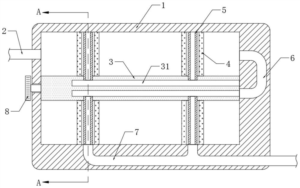
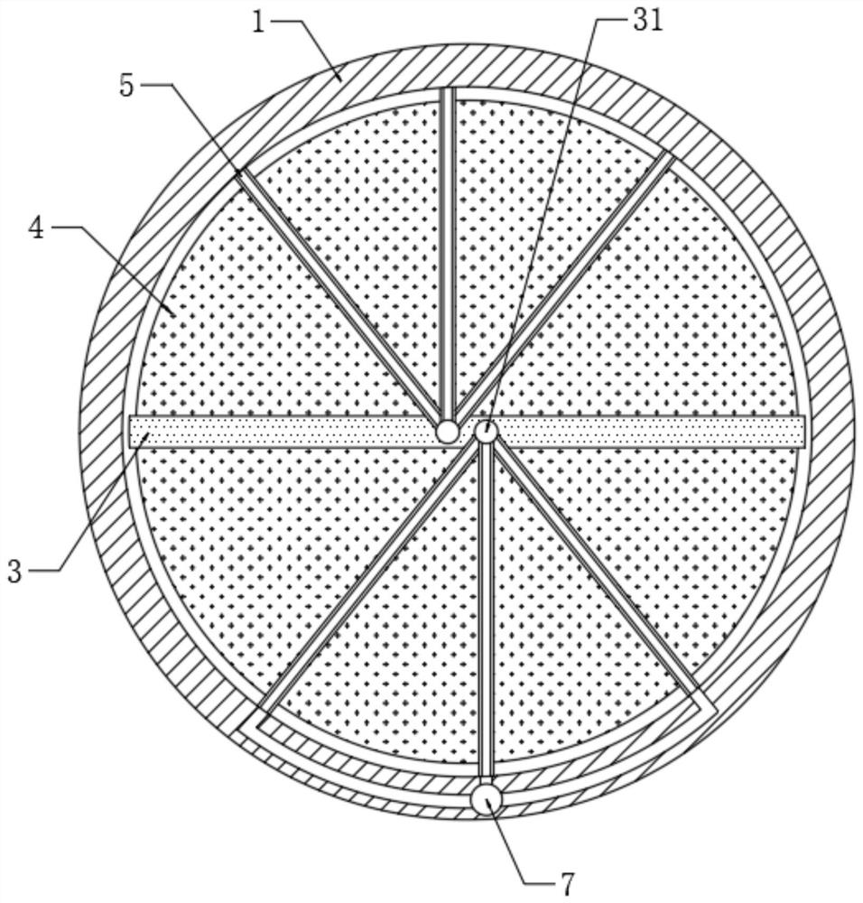
[0020] refer to Figure 1-2 , a low-consumption vehicle air filter, including a housing 1, the side wall of the housing 1 is installed with an air intake pipe 2 communicating with the inside, and the inner bottom of the housing 1 is also equipped with an air outlet pipe 7, the housing 1 A partition 3 is rotatably connected to the inner wall of the partition. It should be noted that the side wall of the partition 3 is against the inner wall of the housing 1 and divides the housing 1 into two chambers that are not connected to each other.

[0021] Both the upper end and the lower end of the partition plate 3 are equipped with a filter element 4, and the installation method of the filter element 4 is an existing mature technical means, which will not be described in detail here. Moreover, the filter element 4 is embedded with a plurality of elastic rubber pipes 5 . It should be noted that the outer walls of the rubber pipes 5 are fixedly connected with the filter element 4 . And...

Embodiment 2

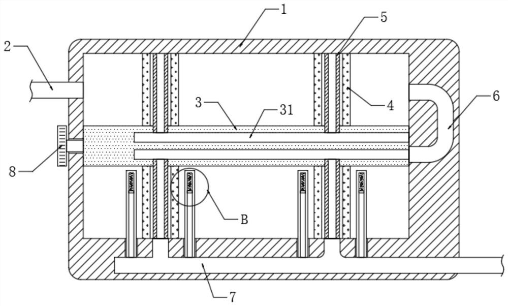
[0028] Referring to 3-4, the difference from the first embodiment is that the inner bottom of the housing 1 is embedded with a plurality of glass sleeves 9 communicating with the air outlet pipe 7, and every two adjacent glass sleeves are arranged symmetrically on the filter element 4 The two sides of the glass sleeve 9 are slidably connected with a slider 10 , and the side wall of the slider 10 is fixedly connected with a silk 101 .

[0029] It should be noted that the side wall of the slider 10 is in close contact with the inner wall of the glass sleeve 9 . (Specifically in the manufacturing process, the silk 101 is fixedly arranged on a part of the lower side of the slider 10, which can ensure that when the slider 10 moves up and down, the silk 101 can rub against the glass sleeve 9, and the slider 10 and the glass sleeve 9 There is also good airtightness between them).

[0030] The upper end of the slide block (10) is elastically connected to the inner top of the glass sl...


PUM


Abstract

The invention discloses a low-consumption vehicle air filter, which comprises a casing, the side wall of the casing is installed with an air intake pipe communicating with the interior thereof, and the inner bottom of the casing is also equipped with an air outlet pipe, so that The inner wall of the housing is rotatably connected with a partition, the upper end and the lower end of the partition are equipped with a filter element, and a plurality of elastic rubber pipes are embedded in the filter element, and the rubber pipe below the partition is connected to the The air outlet pipe is connected, the side wall of the partition is provided with two air guide grooves, the housing is embedded with a U-shaped pipe, and one end of the U-shaped pipe communicates with the inside of the housing, and the U-shaped pipe The other end communicates with one of the air guide grooves. The invention shakes off the dust and other particles adsorbed on the filter element under the partition by forcing the rubber pipe to shrink and restore continuously, so as to ensure that the filter element can be used multiple times, greatly reducing the replacement frequency of the filter element, thereby reducing the maintenance cost of the car.

Description

technical field [0001] The invention relates to the technical field of equipment related to auto parts, in particular to a low-consumption vehicle air filter. Background technique [0002] An air filter is a filter, also known as an air filter cartridge or style. It is mainly used for air filtration in engineering locomotives, automobiles, agricultural locomotives, laboratories, aseptic operating rooms and various precision operating rooms. [0003] Among them, for the air filter on the car, after using it for a period of time, after a large amount of dust and other particles are adsorbed on the filter element in the air filter, its filtering performance will be greatly reduced, which will eventually affect the work of the engine. The filter element in the car air filter is often replaced frequently, which increases the maintenance cost of the car. Contents of the invention [0004] The purpose of the present invention is to solve the shortcomings in the prior art, and p...

Claims


Application Information

Patent Timeline
Patent Type & Authority Patents(China)
IPC IPC(8): F02M35/08F02M35/02F02M35/024F02M35/16
CPCF02M35/086F02M35/0217F02M35/024F02M35/16
Inventor 于世杰
Owner 浙江益新机械股份有限公司
Learn More