
Device for detecting bearing capacity of pile soil composite foundation

A technology of composite foundation and bearing capacity, which is used in foundation structure engineering, on-site foundation soil survey, construction, etc., can solve the problems of load-bearing plate tilt, load-bearing plate dumping, accelerated jack damage, etc., to avoid direct dumping and long recovery time. , the effect of prolonging the pouring time

Inactive Publication Date: 2020-07-31
孙景辉
View PDF7 Cites 0 Cited by
  • Summary
  • Abstract
  • Description
  • Claims
  • Application Information

AI Technical Summary

Problems solved by technology

[0003] One is that the center of gravity of the weight deviates too much from the center of gravity of the jack, resulting in a serious inclination of the load-bearing plate. However, the existing load-bearing plate and the hydraulic device are flexibly connected. The device topples over, and the second is that although the entire measurement system can still support stably when the center of gravity of the weight deviates too much from the center of gravity of the jack, the center of gravity of the weight and the center of gravity of the jack deviate slightly, which will cause deviations in the measurement of foundation subsidence and accelerate the jack The third is that the load-bearing device does not have an indicating device that can indicate the direction of force deviation, which is not easy to observe and judge how to adjust the weight

Method used


Image

  • Device for detecting bearing capacity of pile soil composite foundation
  • Device for detecting bearing capacity of pile soil composite foundation
  • Device for detecting bearing capacity of pile soil composite foundation

Examples


Embodiment 1

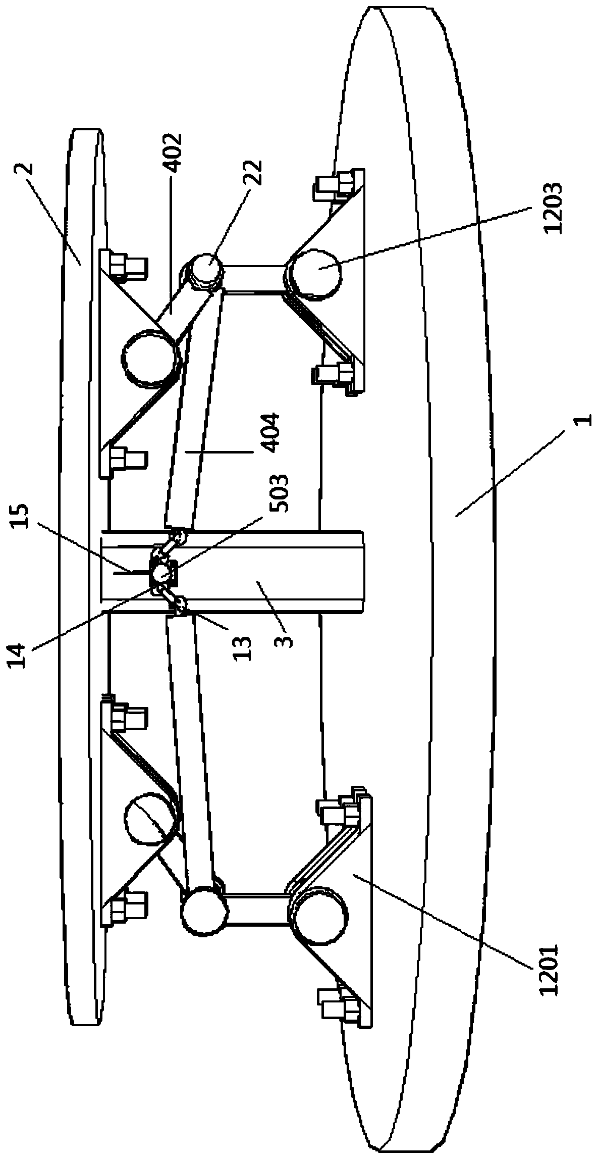
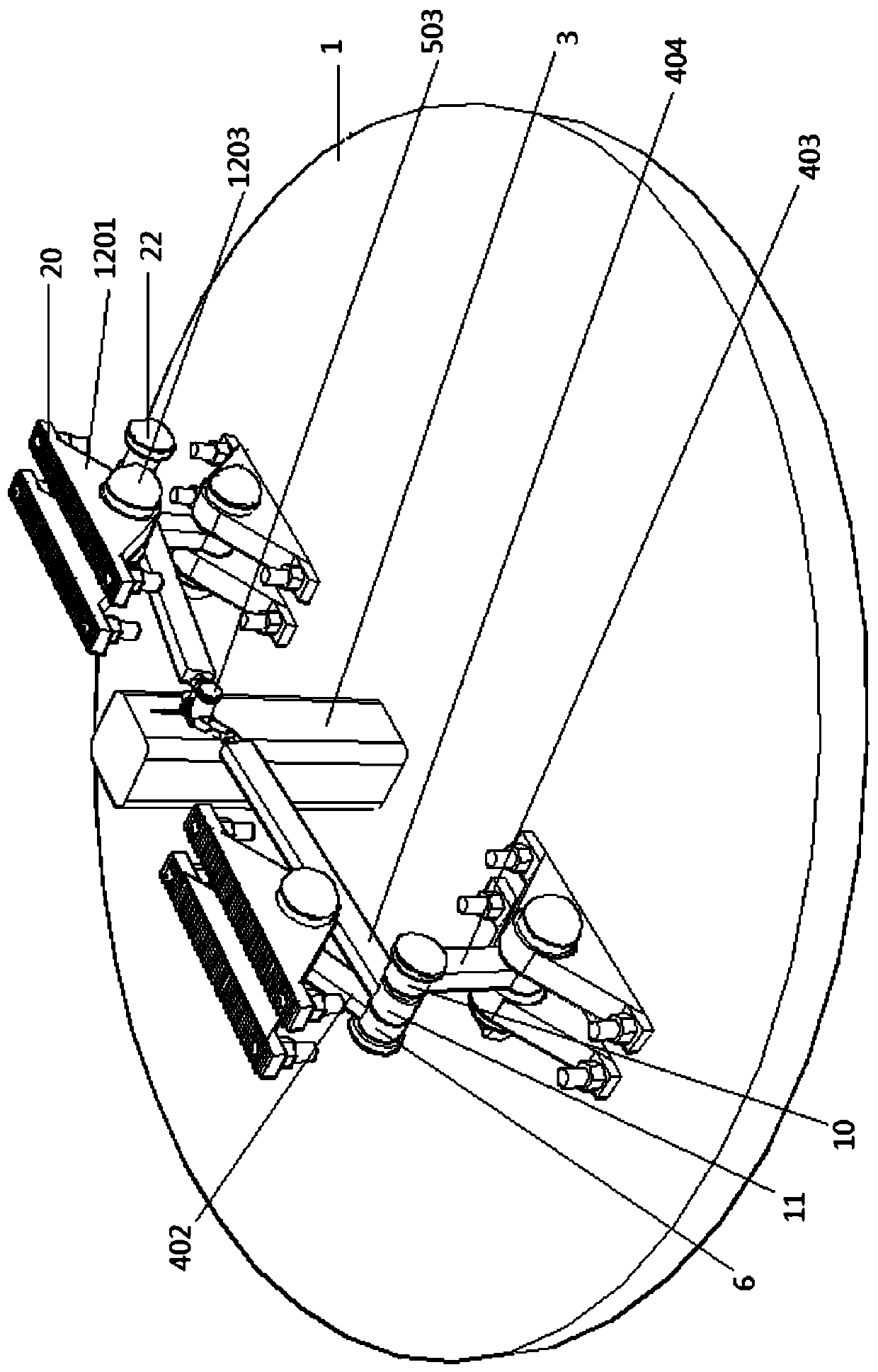
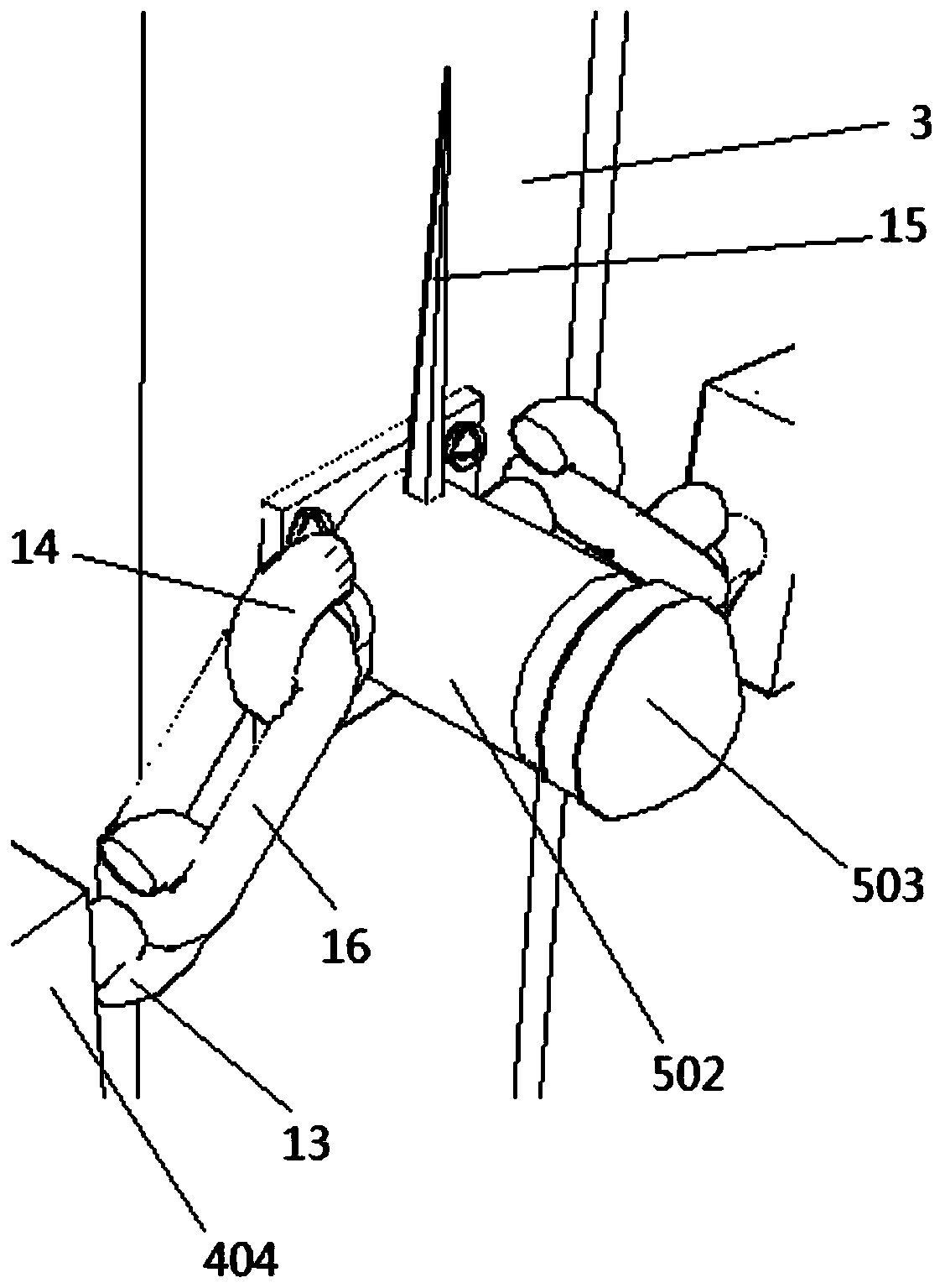
[0030] refer to Figure 1-4 , Figure 6 and Figure 7, this embodiment 1 introduces a device for testing the bearing capacity of pile-soil composite foundations, the device column includes a load-bearing plate 1, a load-bearing plate 2 2, a support pile 3, a balance adjustment mechanism 4 and an inclination indicating mechanism 5; The bottom end of support pile 3 is fixedly connected with load-bearing plate one 1, the top of support pile 3 is movably connected with load-bearing plate two 2, and the centerlines of support pile 3, load-bearing plate one 1 and load-bearing plate two 2 coincide; support pile 3, load-bearing plate one 1 and the load-bearing plate 2 form a rigid and movable support device, the top of the support pile 3 is connected with the load-bearing plate 2 movably, and the load-bearing plate 2 can tilt left and right with the 3 fulcrums of the support pile when the force is uneven There are two balance adjustment mechanisms 4, two balance adjustment mechanism...

Embodiment 2

[0032] refer to Figure 1-4 , Figure 6 and Figure 7 , on the basis of the first embodiment, this embodiment further defines the rotation angle of the balance adjustment arm one 402, and by limiting the rotation angle, the stable state of the balance adjustment mechanism 4 during operation is ensured.

[0033] This embodiment 1 introduces a device for testing the bearing capacity of pile-soil composite foundations. The device column includes a load-bearing plate 1, a load-bearing plate 2, a supporting pile 3, a balance adjustment mechanism 4, and an inclination indicating mechanism 5; The bottom of the pile 3 is fixedly connected with the load-bearing plate 1, and the top of the support pile 3 is movably connected with the load-bearing plate 2 2, and the centerlines of the support pile 3, the load-bearing plate 1 and the load-bearing plate 2 coincide; And a support device with both rigidity and mobility is formed between the load-bearing plates 2 and 2. The top of the suppo...

Embodiment 3

[0035] refer to Figure 1-7 , on the basis of Embodiment 2: This embodiment elaborates the connection mode between bearing 1, bearing 2 and bearing 3 and the movable shaft, which is beneficial to the connection between bearing 1, bearing 2 and bearing 3 and the movable shaft 401 Fixed connection.

[0036] Wherein, the movable shaft 401 is provided with a first bearing groove 17, a second bearing groove 18 and a third bearing groove 19, the first bearing is engaged in the first bearing groove 17, the second bearing is engaged in the second bearing groove 18, The three bearings are engaged in the three bearing grooves 19 inside. Bearing 1 is engaged in bearing 1 groove 17, bearing 2 is engaged in bearing 2 groove 18 and bearing 3 is engaged in bearing 3 groove 19, so that bearing 1, bearing 2 and bearing 3 can be guaranteed The firmness of the connection on the 401.


PUM


Abstract

The invention provides a device for detecting the bearing capacity of a pile soil composite foundation. The device comprises a bearing plate I, a bearing plate II, a supporting pile, a balance adjusting mechanism and an inclination indicating mechanism. The bottom end of the supporting pile is fixedly connected with the bearing plate I. The top end of the supporting pile is movably connected withthe bearing plate II. The balance adjusting mechanism comprises a moving shaft, a balance adjusting arm I, a balance adjusting arm II and a balance adjusting arm III. A bearing I, a bearing II and a bearing III fixedly sleeve the moving shaft. A rotating sleeve I, a rotating sleeve II and a rotating sleeve III are further arranged. An upper limiting block and a lower limiting block are arranged inthe rotating sleeve I. A baffle is fixedly arranged on the moving shaft. The inclination indicating mechanism comprises a fixed shaft and a rotating sleeve. A pair of hooks II are symmetrically arranged on the left side and the right side of the rotating sleeve. An indicating needle is fixedly connected to the middle position of the rotating sleeve. According to the device, when the center of gravity of a bearing block and the center of gravity of a hydraulic device are not in a straight line, the inclination degree of the bearing plate II can be buffered, and the stressing and inclination direction of a buffering plate are indicated.

Description

technical field [0001] The invention belongs to the technical field of building equipment, in particular to a device for testing the bearing capacity of pile-soil composite foundations. Background technique [0002] Static pressure measurement of foundation bearing capacity is the most accurate and commonly used method for measuring foundation bearing capacity. During the implementation of the static pressure measurement method, support beams need to be set to maintain the stability of the entire measurement mechanism during the process of stacking weights. After the heavy blocks are stacked neatly, adjust the height of the jack so that both ends of the secondary beam are away from the supporting beam, so that the pressure of all the heavy blocks can be transmitted to the foundation to be measured through the jack, and then the subsidence of the foundation can be measured. During the actual operation of the secondary beam leaving the supporting beam, there may be the follow...

Claims


Application Information

Patent Timeline
IPC IPC(8): E02D1/00E02D1/08
CPCE02D1/00E02D1/08
Inventor 孙景辉谢瑞石攀吴磊杰
Owner 孙景辉
Learn More