
Film type wall conductive device

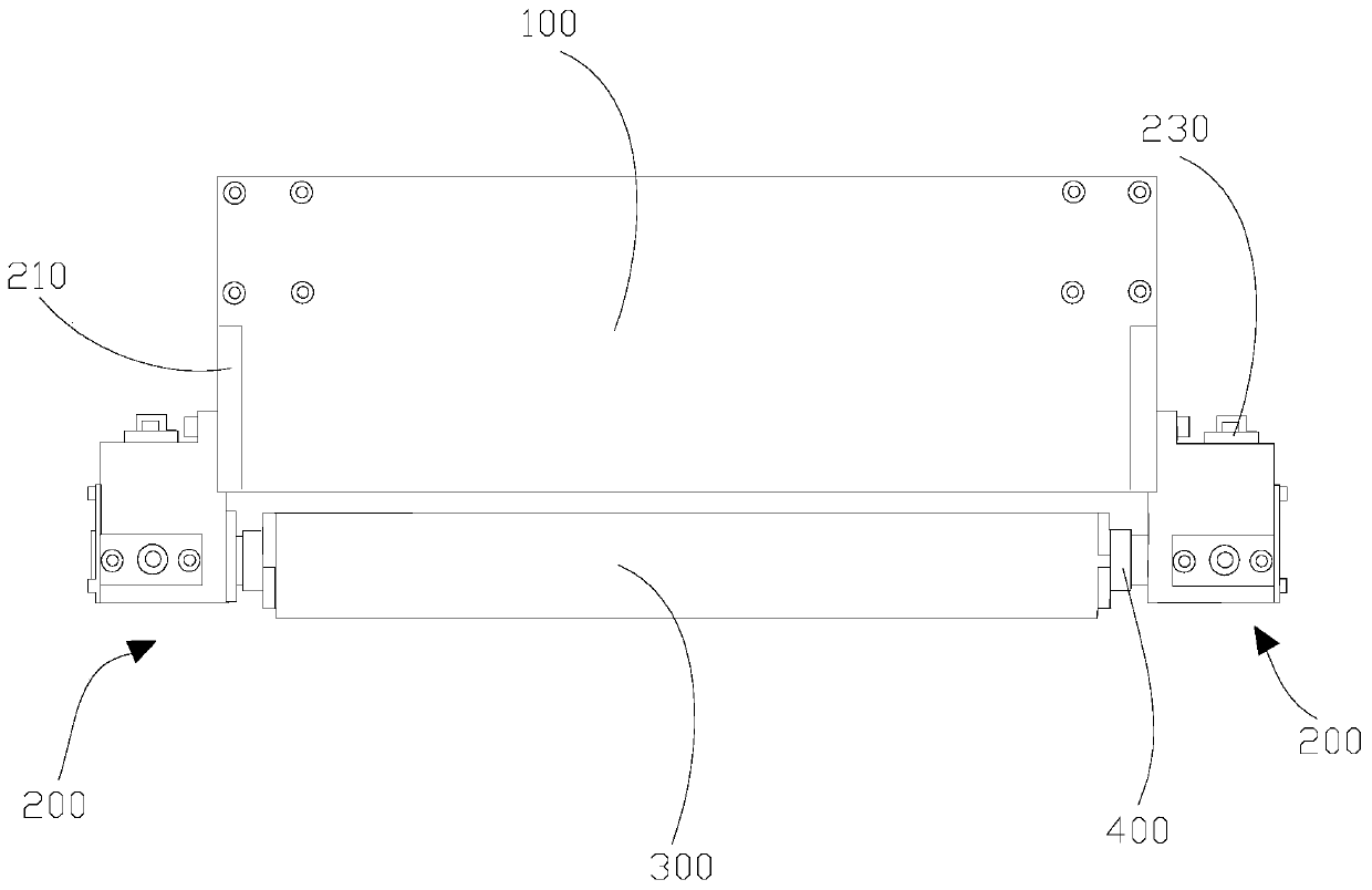
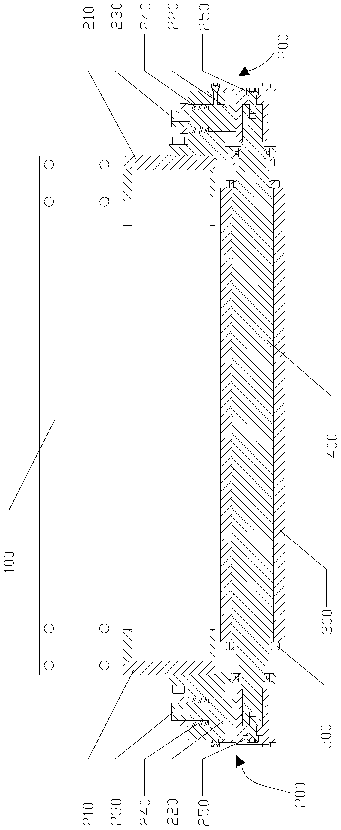
A conductive device and membrane wall technology, applied in auxiliary devices, rotating current collectors, circuits, etc., can solve the problems of unstable flow of conductive current, large wear of tubes, and influence on welding quality, so as to achieve simple structure and prevent The effect of accumulating welding slag and ensuring flow stability

Pending Publication Date: 2020-07-28
POURIN WELDING ENG
View PDF0 Cites 0 Cited by
  • Summary
  • Abstract
  • Description
  • Claims
  • Application Information

AI Technical Summary

Problems solved by technology

Specifically, the traditional conduction method is to apply pressure to the steel body current collector to maintain stable contact with the tube row to complete the conduction, but there are several shortcomings in this method: 1. Direct surface-to-surface contact friction, the wear of the tube row The degree is large and the replacement is frequent; 2. The accumulation of welding slag generated after welding is easy to cause damage to the tube; 3. The flow of conductive current on the tube row is unstable, which may affect the welding quality

Method used


Image

  • Film type wall conductive device
  • Film type wall conductive device

Examples


Embodiment Construction

[0022] This part will describe the specific embodiment of the present invention in detail, and the preferred embodiment of the present invention is shown in the accompanying drawings. Each technical feature and overall technical solution of the invention, but it should not be understood as a limitation on the protection scope of the present invention.

[0023] In the description of the present invention, it should be understood that the orientation descriptions, such as up, down, front, back, left, right, etc. indicated orientations or positional relationships are based on the orientations or positional relationships shown in the drawings, and are only In order to facilitate the description of the present invention and simplify the description, it does not indicate or imply that the device or element referred to must have a specific orientation, be constructed and operated in a specific orientation, and thus should not be construed as limiting the present invention.

[0024] I...


PUM


Abstract

The invention discloses a film type wall conductive device and is used for providing electric power for tube bank welding. The film type wall conductive device comprises a conductive mechanism, a barmaterial which can roll on a tube row, and a long shaft which is connected with the conductive mechanism, wherein the bar is mounted on the outer side of the long shaft. Compared with the prior art, the film type wall conductive device is advantaged in that the device is simple in structure and reasonable in design, the abrasion degree of the tube row during welding can be reduced, welding slag accumulation is prevented, that the conductive current on the tube row has stability is guaranteed, and reliability of film type wall tube row welding can be improved.

Description

technical field [0001] The invention relates to the field of membrane wall pipe row welding, in particular to a membrane wall conductive device. Background technique [0002] At present, the technology of multi-pipe side-by-side welding in the membrane wall industry has developed to a mature and stable technical level. The stability of multi-pipe side-by-side welding quality is deeply concerned by the pipe row production factory. According to experiments, the conductivity of the tube row Good or bad will directly affect the welding quality, such as large spatter, undercut and many other problems are caused by poor conductivity. Specifically, the traditional conduction method is to apply pressure to the steel body current collector to maintain stable contact with the tube row to complete the conduction, but there are several shortcomings in this method: 1. Direct surface-to-surface contact friction, the wear of the tube row The degree is large and the replacement is frequent...

Claims


Application Information

Patent Timeline
Patent Type & Authority Applications(China)
IPC IPC(8): H01R39/64H01R4/60B23K37/00
CPCB23K37/00H01R4/60H01R39/643
Inventor 李海生陈学森汤振胜
Owner POURIN WELDING ENG
Learn More