
Display panel and display device

A display panel and display area technology, which is applied in the direction of static indicators, instruments, semiconductor devices, etc., can solve the problems of sub-pixel luminous brightness difference, affecting the display performance of the display panel, and screen splitting, so as to reduce the difference in attenuation degree and improve Split screen phenomenon, the effect of improving display performance

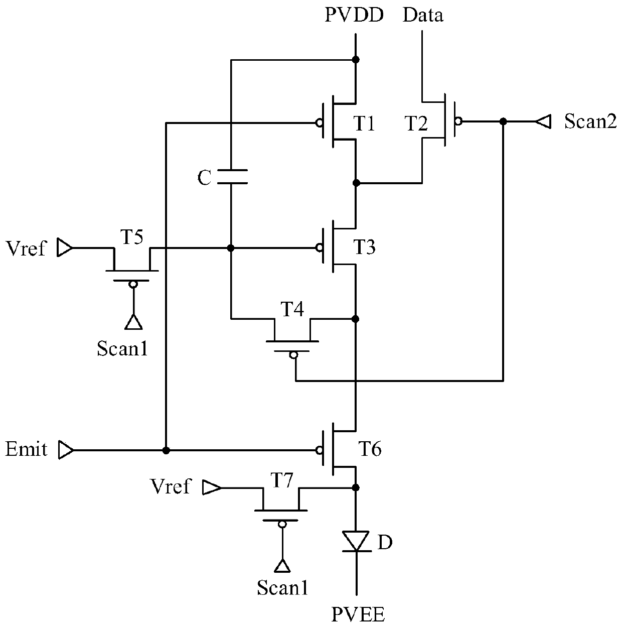
Active Publication Date: 2020-07-28
WUHAN TIANMA MICRO ELECTRONICS CO LTD
View PDF13 Cites 2 Cited by
  • Summary
  • Abstract
  • Description
  • Claims
  • Application Information

AI Technical Summary

Problems solved by technology

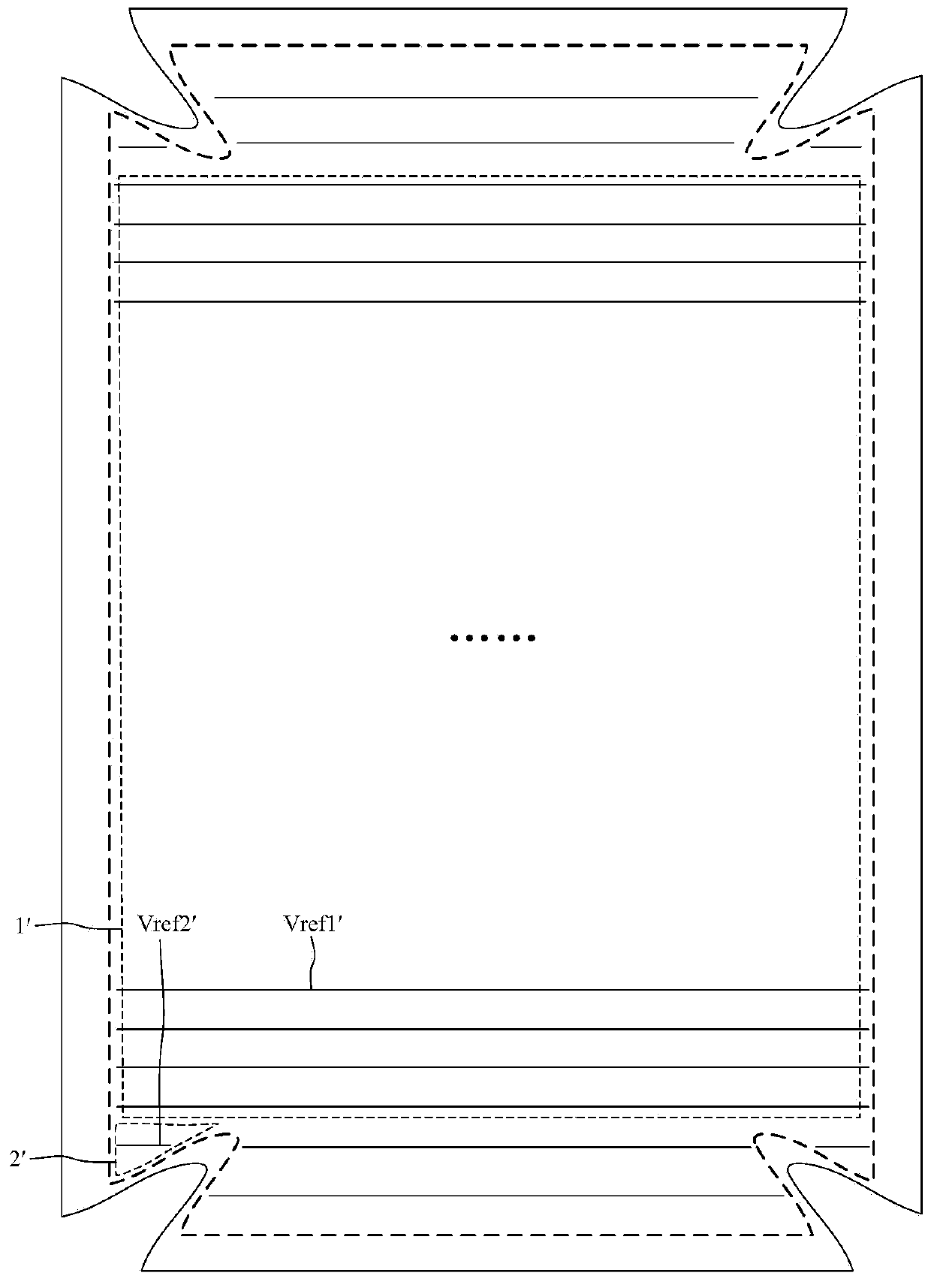
However, for a display panel with a different shape, limited by the shape of the display panel, the lengths of the reference signal lines set in the display panel are different, and the corresponding loads are also different, which leads to the fact that the reference signal is on different reference signal lines. Different degrees of attenuation during uplink transmission lead to different reset degrees of sub-pixels electrically connected to different reference signal lines, which in turn leads to differences in luminous brightness of sub-pixels, resulting in split-screen phenomenon in the picture displayed on the display panel, which affects the display of the display panel. performance

Method used


Image

  • Display panel and display device
  • Display panel and display device
  • Display panel and display device

Examples


Embodiment Construction

[0029] In order to better understand the technical solutions of the present invention, the embodiments of the present invention will be described in detail below with reference to the accompanying drawings.

[0030] It should be clear that the described embodiments are only a part of the embodiments of the present invention, rather than all the embodiments. Based on the embodiments of the present invention, all other embodiments obtained by those of ordinary skill in the art without creative work shall fall within the protection scope of the present invention.

[0031] The terms used in the embodiments of the present invention are only for the purpose of describing specific embodiments, and are not intended to limit the present invention. The singular forms of "a", "said" and "the" used in the embodiments of the present invention and the appended claims are also intended to include plural forms, unless the context clearly indicates other meanings.

[0032] It should be understood th...


PUM


Abstract

The embodiment of the invention provides a display panel and a display device, relates to the technical field of display, and aims to improve the split screen phenomenon. The display panel comprises adisplay area provided with sub-pixels, a reference bus, reference signal lines, and a load compensation structure, wherein the reference signal lines are connected with the sub-pixels, at least partof the reference signal lines are connected with the reference bus through the load compensation structure, the load compensation structure comprises a load compensation wire connected with the reference bus, a signal transmission wire connected with the reference signal wire, and at least two switches connected between the load compensation wire and the signal transmission wire, the reference signal lines comprise a first reference line and a second reference line, and the first reference line is shorter than the second reference line. The display panel is advantaged in that in the load compensation structure connected with the first reference line, equivalent loads of the load compensation line and the signal transmission line which are connected through the switches are LA1, in the loadcompensation structure connected with the second reference line, equivalent loads of the load compensation line and the signal transmission line which are connected through the switch are LA2, and LA1 is larger than LA2.

Description

【Technical Field】 [0001] The present invention relates to the field of display technology, in particular to a display panel and a display device. 【Background technique】 [0002] In display technology, Organic Light Emitting Diode (OLED) display panels have been widely used due to their advantages such as fast response speed, wide viewing angle, high brightness, and low power consumption. [0003] The display area of ​​the OLED display panel is provided with multiple reference signal lines electrically connected to the sub-pixels for providing reference signals to the sub-pixels to reset the gates of the driving transistors and the anodes of the light-emitting diodes in the sub-pixels. However, for display panels with irregular shapes, limited by the shape of the display panel, the length of the reference signal line provided in the display panel is different, and the corresponding load is also different, which causes the reference signal to be on different reference signal lines. ...

Claims


Application Information

Patent Timeline
Patent Type & Authority Applications(China)
IPC IPC(8): H01L27/32H01L51/52G09G3/3225
CPCG09G3/3225G09G2320/0242G09G2320/0606H10K59/131H10K50/86
Inventor 费日锂周瑞渊夏志强王亚威
Owner WUHAN TIANMA MICRO ELECTRONICS CO LTD
Learn More