Construction device for installation groove of load-bearing steel frame of a house

A technology for construction devices and installation grooves, which is applied in the direction of grinding drive devices, manufacturing tools, metal processing equipment, etc., can solve the problems of large gaps, rough side walls of installation grooves, and different depths of H-shaped steel installation grooves. Grinding effect, increasing connection effect, increasing grinding efficiency effect

Inactive Publication Date: 2020-12-01
湖北泓博锐建设工程有限公司
View PDF8 Cites 0 Cited by
  • Summary
  • Abstract
  • Description
  • Claims
  • Application Information

AI Technical Summary

Problems solved by technology

[0004] 1. The grinding of H-shaped steel is generally carried out by manual grinding. In this way, the grinding precision of the H-shaped steel installation groove is low, and the side wall of the installation groove is not smooth, resulting in the connection between the H-shaped steel and the steel that cannot be inserted or the gap after insertion. Major issues;
[0005] 2. It is cumbersome to manually set the bevel angle of the H-beam installation groove, and the depth of the bevel opening on the H-beam installation groove is different

Method used


Image

  • Construction device for installation groove of load-bearing steel frame of a house
  • Construction device for installation groove of load-bearing steel frame of a house
  • Construction device for installation groove of load-bearing steel frame of a house

Examples


Embodiment Construction

[0028] In order to make the technical means, creative features, goals and effects achieved by the present invention easy to understand, the present invention will be further described below in conjunction with specific illustrations. It should be noted that, in the case of no conflict, the embodiments in the present application and the features in the embodiments can be combined with each other.

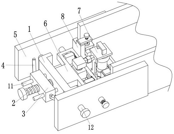
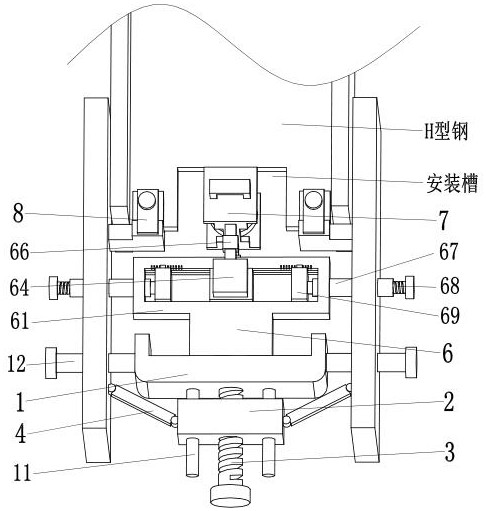
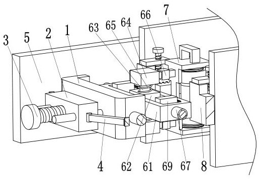
[0029] Such as Figure 1 to Figure 5As shown, a construction device for the installation groove of a load-bearing steel frame of a house includes a fixed plate 1, an adjusting bolt 2, a moving block 3, a linkage rod 4, an outer clamping plate 5, a moving mechanism 6 and a grinding mechanism 7. The fixed plate 1 The middle part of the left side of the fixed plate 1 is connected with the right end of the adjusting bolt 2 through a bearing, and the middle part of the adjusting bolt 2 is connected with the moving block 3 through thread fit, and a limit rod is arranged on the left front a...


PUM


Abstract

The invention relates to a construction device for a mounting groove of a bearing steel frame of a house. The construction device comprises a fixed plate, an adjusting bolt, a moving block, linking rods, outer clamping plates, a moving mechanism and a grinding mechanism. The middle of the left side surface of the fixed plate is connected to the right end of the adjusting bolt through a bearing, the middle of the adjusting bolt is connected to the moving block in a threaded fit manner, limiting rods are arranged at the front and back ends of the left side surface of the fixed plate, the left end of each limiting rod penetrates the moving block, linking rods are mounted on the front and back side surfaces of the moving block through hinges, and the outer clamping plate is mounted at the outer end of each linking rod through a hinge. The construction device can solve the problems that in order to grind the mounting groove of H-shaped steel in the prior art, the grinding precision of the mounting groove of the H-shaped steel is low and the side wall of the mounting groove is unsmooth as the H-shaped steel is commonly ground manually, resulting in inability of inserting the H-shaped steel and steel or relatively large gap after insertion and the like.

Description

technical field [0001] The invention relates to the technical field of building construction, in particular to a construction device for installing a groove for a load-bearing steel frame of a house. Background technique [0002] The main support structure of houses in modern buildings is often supported by steel structures. The steel structure is mainly composed of beams, steel columns, steel trusses and other components made of section steel and steel plates. Welds, bolts, etc. are used between components or parts. or rivet connection. The steel structure has the advantages of light weight and easy construction. [0003] The most commonly used steel in steel structure is H-shaped steel. When connecting H-shaped steel with other steels, it is necessary to open a mounting groove in the middle. Insert the steel to be connected into the mounting groove of H-shaped steel and lock the bolt through the preset round hole. connection, and then weld the joint between the H-shaped ...

Claims


Application Information

Patent Timeline
Patent Type & Authority Patents(China)
IPC IPC(8): B24B19/02B24B41/04B24B41/06B24B47/20B24B47/22
CPCB24B19/02B24B41/04B24B41/06B24B47/20B24B47/22
Inventor 严斌张松周晓华
Owner 湖北泓博锐建设工程有限公司
Why Eureka
Try Eureka