
Electric liquid transferring device

An electric and pipetting technology, which is applied in the direction of analyzing materials and instruments, can solve the problems of large harmful overturning moment, large vertical distance, and high price, and achieve the effect of the shortest vertical distance, small mechanical vibration and low price

Pending Publication Date: 2020-07-24
PREMEDICAL LAB
View PDF0 Cites 3 Cited by
  • Summary
  • Abstract
  • Description
  • Claims
  • Application Information

AI Technical Summary

Problems solved by technology

[0008] The purpose of the present invention is to provide an electric liquid pipetting device, which can not only solve the problem of high price in the existing technology of using small-diameter high-speed motors, but also solve the problem of using a small-diameter high-speed motor on the premise of meeting the requirements of the center distance of the container foundation. There is a large distance between the reciprocating axis of the pipetting actuator and the vertical line of the mechanism fulcrum in the conventional motor, and the large harmful overturning moment and fatigue deformation caused by the frequent press-fit connection between the pipetting actuator and the pipetting head along the axis

Method used


Image

  • Electric liquid transferring device
  • Electric liquid transferring device
  • Electric liquid transferring device

Examples


Embodiment Construction

[0054] In order to have a clearer understanding of the technical features, purposes and effects of the present invention, the specific implementation manners of the present invention will now be described with reference to the accompanying drawings. Among them, the use of adjective or adverb modifiers "upper" and "lower", "top" and "bottom", "inner" and "outer", "horizontal" and "vertical", "front" and "back" This is merely to facilitate relative reference between sets of terms and does not describe any particular directional limitation on the modified term. In addition, the terms "first", "second" and so on are only used for descriptive purposes, and cannot be understood as indicating or implying relative importance or implicitly specifying the number of indicated technical features. Therefore, the definition of "first" , "second", etc. may expressly or implicitly include one or more of these features. In the description of the present invention, unless otherwise specified, ...


PUM


Abstract

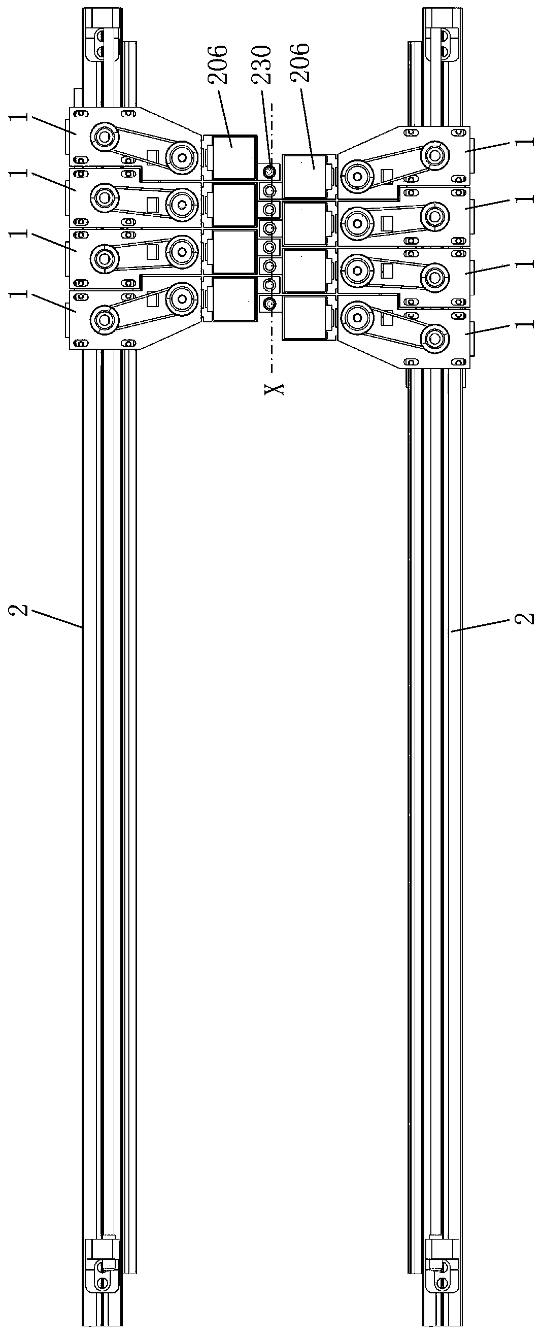
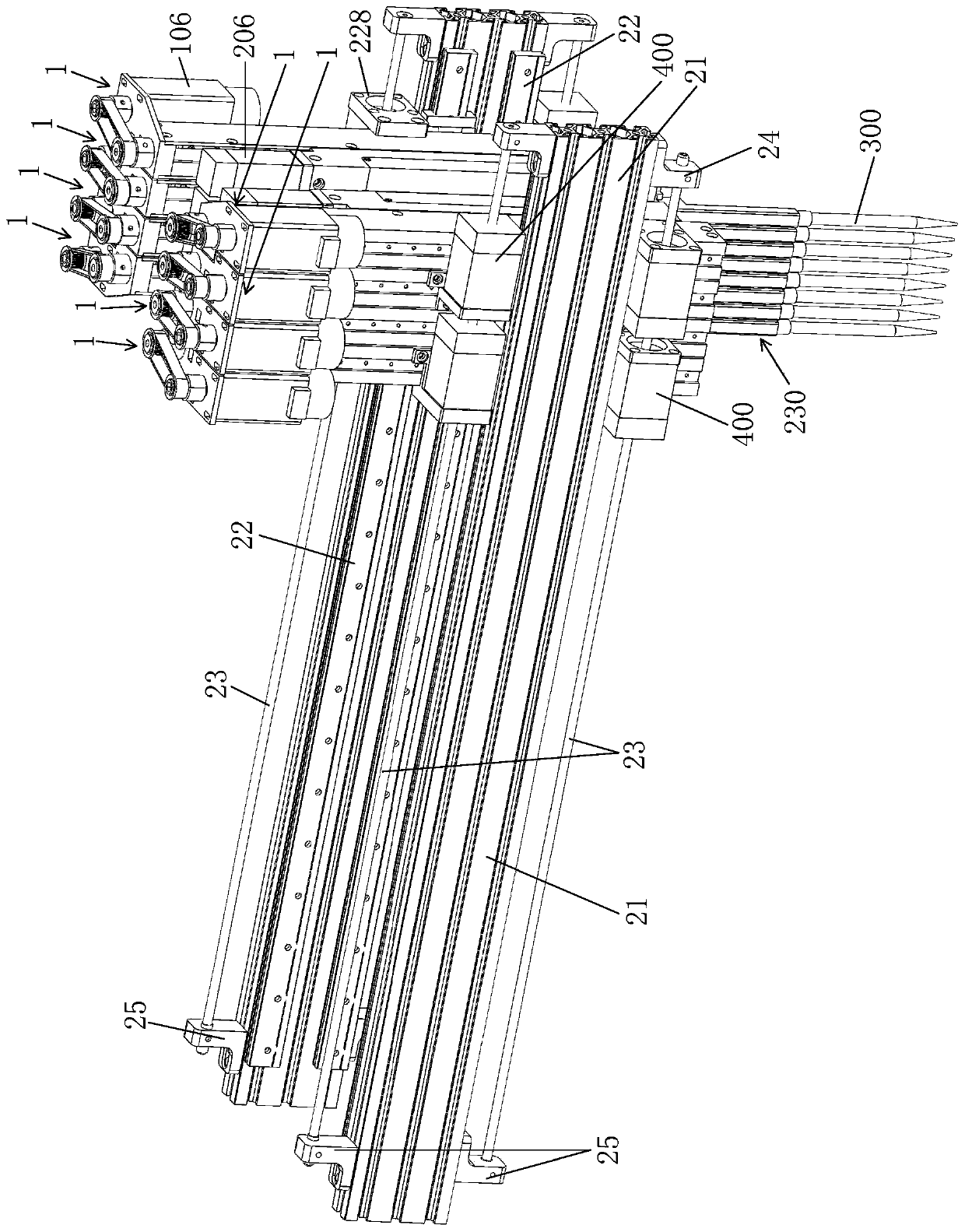
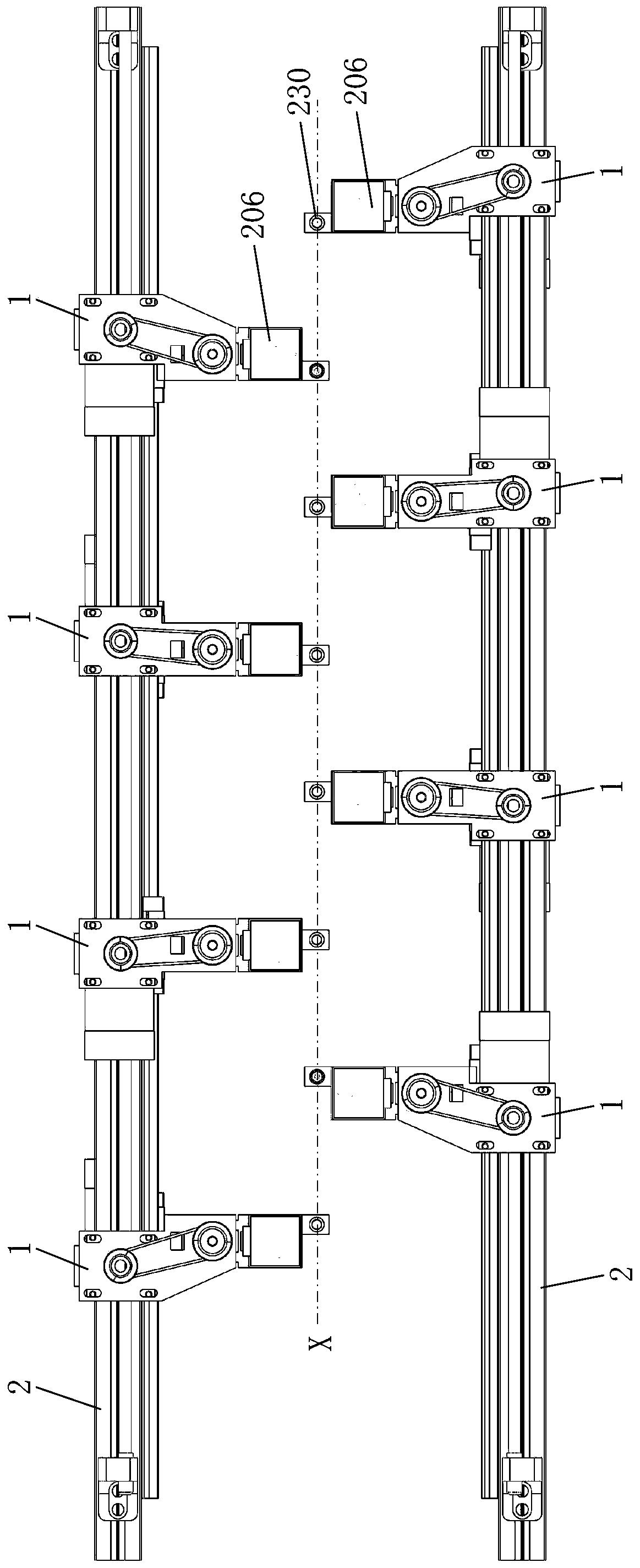
The invention provides an electric liquid transferring device. The electric liquid transferring device comprises two sliding tables symmetrically arranged on the two opposite sides of a central transverse shaft, wherein at least one electric liquid transferring device is installed on each sliding table; each electric liquid transferring device comprises a loading mechanism and an executing mechanism; each loading mechanism comprises a supporting frame and a first motor; each executing mechanism comprises a rack, a second motor and a liquid transferring assembly; the liquid transferring assemblies are positioned at the central transverse shaft; the second motors are positioned on the outer side of the central transverse shaft; the first motors are positioned on the outer side of a supporting point; and when the electric liquid transferring devices on the two sliding tables are gathered side by side, the liquid transferring assemblies of the electric liquid transferring devices on the two sliding tables are sequentially and alternately arranged at the central transverse shaft along the central transverse shaft. On the premise that the requirement for the center distance of a vessel foundation is met, the common motors are adopted, the shortest distance between the reciprocating motion axis of the executing mechanisms and the vertical line between the supporting points is achieved, and harmful overturning moment and fatigue deformation generated when the executing mechanisms are downwards connected with liquid transferring heads in a frequently-pressed mode along the axes of the executing mechanisms are reduced.

Description

technical field [0001] The invention relates to a sample adding device, in particular to an electric pipetting device. Background technique [0002] In the detection work in the fields of medicine, food, biology, etc., it is necessary to carry out a lot of pre-processing work on biological materials and samples (usually in liquid state). The high-throughput automated biological sample automatic processing system can be completed in batches in a short time Pipetting, adding samples, mixing and other operations, as well as the preparation of templates for a large number of biological samples. [0003] The electric pipette is the core technical unit in the automatic processing system of biological samples. When electric pipettes are used in combination, because the working objects are various and standardized vessels, the distance between the movement axis of any pipette and the movement axis of the side pipette must meet the basic center distance of the conventional vessel. ...

Claims


Application Information

Patent Timeline
IPC IPC(8): G01N35/10
CPCG01N35/1011G01N35/1065G01N2035/1076
Inventor 范光伟
Owner PREMEDICAL LAB
Learn More