Mechanical arm monitoring equipment

A technology for monitoring equipment and robotic arms, applied in the directions of manipulators, manufacturing tools, etc., can solve problems such as stopping, and achieve the effect of high reliability and simple structure

Pending Publication Date: 2020-07-24
深圳市鼎拓达机电有限公司
View PDF7 Cites 1 Cited by
  • Summary
  • Abstract
  • Description
  • Claims
  • Application Information

AI Technical Summary

Problems solved by technology

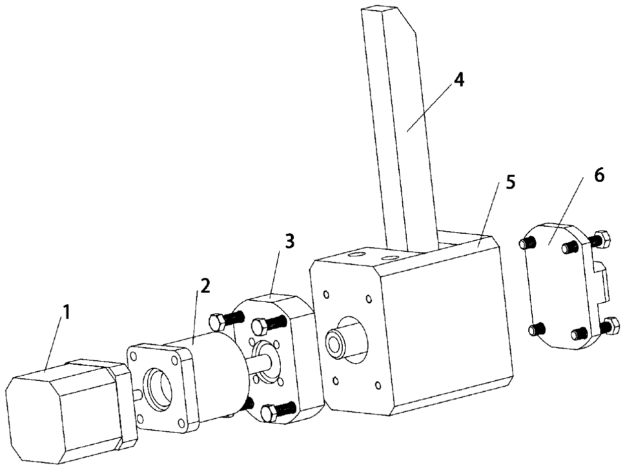
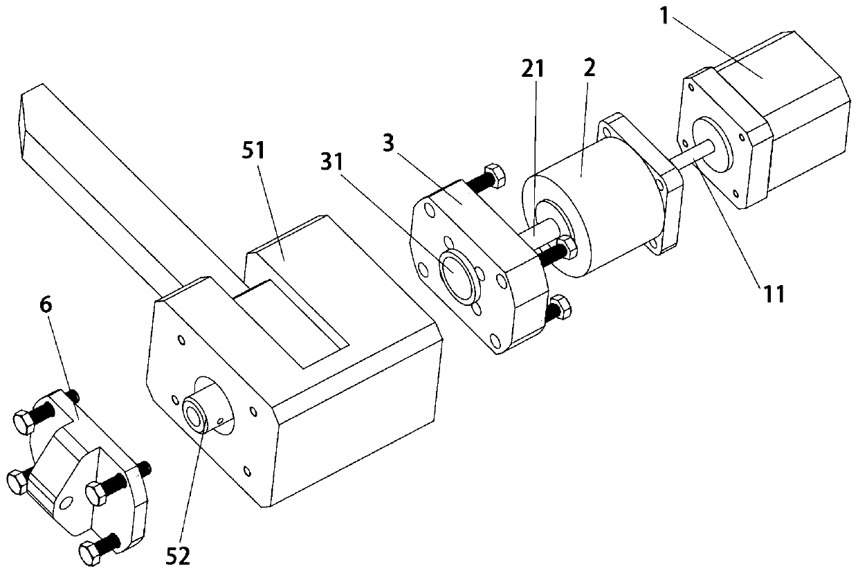
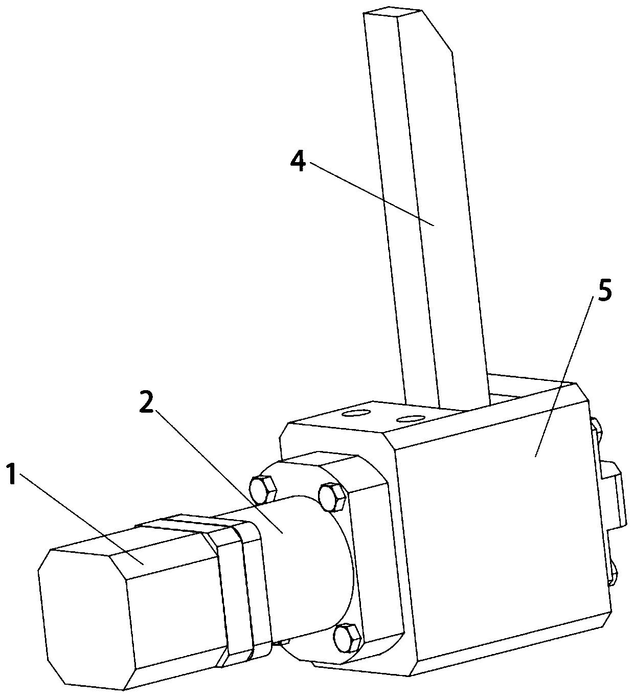
[0003] This application aims to solve the technical problem that the existing mechanical arm often stops before moving to the target position due to external factors such as mechanical friction or excessive load, and provides a monitoring device for the mechanical arm

Method used


Image

  • Mechanical arm monitoring equipment
  • Mechanical arm monitoring equipment
  • Mechanical arm monitoring equipment

Examples


Embodiment Construction

[0037] It should be understood that the specific embodiments described here are only used to explain the present application, and are not intended to limit the present application.

[0038] The technical solutions in the embodiments of the application will be clearly and completely described below in conjunction with the accompanying drawings in the embodiments of the application. Obviously, the described embodiments are only part of the embodiments of the application, not all implementations example. Based on the embodiments in this application, all other embodiments obtained by persons of ordinary skill in the art without creative efforts fall within the protection scope of this application.

[0039] It should be noted that the terms "comprising", "comprising" and "having" in the specification and claims of the present application and the above drawings and any variations thereof are intended to cover non-exclusive inclusion. For example, a process, method, system, product ...


PUM


Abstract

The invention provides mechanical arm monitoring equipment applied to the field of mechanical automation. The mechanical arm monitoring equipment comprises a control circuit board, a brushless motor,a gear speed reduction box, a mechanical arm movable piece and a plurality of hall sensors. The mechanical arm movable piece comprises a support and a drive shaft arranged in the support. The multiplehall sensors are evenly distributed around a rotor of the brushless motor. The control circuit board is arranged in the brushless motor and connected with the brushless motor and the multiple hall sensors. A first output shaft of the brushless motor is connected into the gear speed reduction box, a second output shaft of the gear speed reduction box is connected into the support and adaptively connected with the drive shaft, the drive shaft is fixed to a mechanical arm so as to drive the mechanical arm to move in the support, the rotation angle of the mechanical arm is accurately detected, and the position of a swing arm can be obtained in real time. The system structure is simple, reliability is high, and meanwhile closed-loop position control can be added.

Description

technical field [0001] The present application relates to the technical field of mechanical automation, in particular to a monitoring device for a mechanical arm. Background technique [0002] In many automation equipment, brushless DC motors are used to control the mechanical arm. Because the existing brushless DC motors cannot do precise position control, they are often used under the influence of external factors such as mechanical friction or excessive load. The swing arm stops before it moves to the target position, and if it is not handled in time, it will cause unpredictable losses. Contents of the invention [0003] The present application aims to solve the technical problem that the existing mechanical arm often stops before moving to the target position due to external factors such as mechanical friction or excessive load, and provides a monitoring device for the mechanical arm. [0004] This application adopts the following technical means to solve technical pr...

Claims


Application Information

Patent Timeline
Patent Type & Authority Applications(China)
IPC IPC(8): B25J19/02B25J13/08
CPCB25J19/02B25J13/087
Inventor 王永禄
Owner 深圳市鼎拓达机电有限公司
Why Eureka
Try Eureka