
Thread taking device for bolt breakage

A bolt, a pair of technology, applied in the field of wire removal device, can solve the problems of difficult positioning of the bolt axis, deviation of the drilling from the center of the circle, affecting work efficiency, etc., to prevent tilting and shaking, stability and accurate position, and simplify wire removal The effect of the process

Pending Publication Date: 2020-07-24
中广核(当涂)新能源有限公司
View PDF1 Cites 2 Cited by
  • Summary
  • Abstract
  • Description
  • Claims
  • Application Information

AI Technical Summary

Problems solved by technology

[0004] However, the above-mentioned device for taking out the broken bolts of fan blades still has obvious defects during use: 1. The above-mentioned device does not have an effective fixing device. , if the drill bit is not placed vertically, it is likely to cause damage to the internal thread of the screw hole. Because the bolt axis is difficult to locate, the drill hole often deviates from the center of the circle, which makes it difficult to take the wire later. At the same time, the abnormal vibration of the drill bit may cause the drill bit to break, and then Increase the difficulty of work; 2. The above-mentioned device can only drill holes and take wires for the bolts. However, in the actual wire-taking work, it is found that most of the bolts are stuck in the threaded holes and will not be easily loosened. It is necessary to add an appropriate loosening agent to promote the loosening of the bolts. , and in the outdoor environment, it is often difficult to find the loosening agent and delay the wire taking time, thereby affecting work efficiency

Method used


Image

  • Thread taking device for bolt breakage
  • Thread taking device for bolt breakage
  • Thread taking device for bolt breakage

Examples


Embodiment Construction

[0025] The following will clearly and completely describe the technical solutions in the embodiments of the present invention with reference to the accompanying drawings in the embodiments of the present invention. Obviously, the described embodiments are only some, not all, embodiments of the present invention. Based on the embodiments of the present invention, all other embodiments obtained by persons of ordinary skill in the art without making creative efforts belong to the protection scope of the present invention.

[0026] see Figure 1-6 , the present invention provides a technical solution:

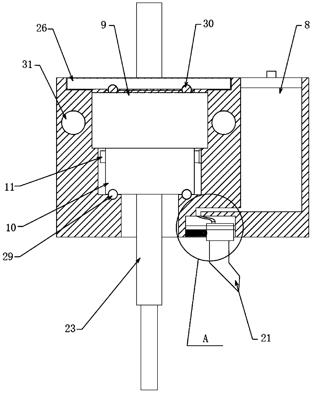
[0027] A bolt fracture wire taking device, comprising a pair of fixing seats 1, the fixing seats 1 on both sides are fixedly connected by a pair of sliding rods 2, the bottoms of the fixing seats 1 on both sides are fixedly installed with neodymium magnet adsorption seats 3, and on the sliding rods 2 A fine-tuning mobile seat 4 is installed in the activity;

[0028] The device is...


PUM


Abstract

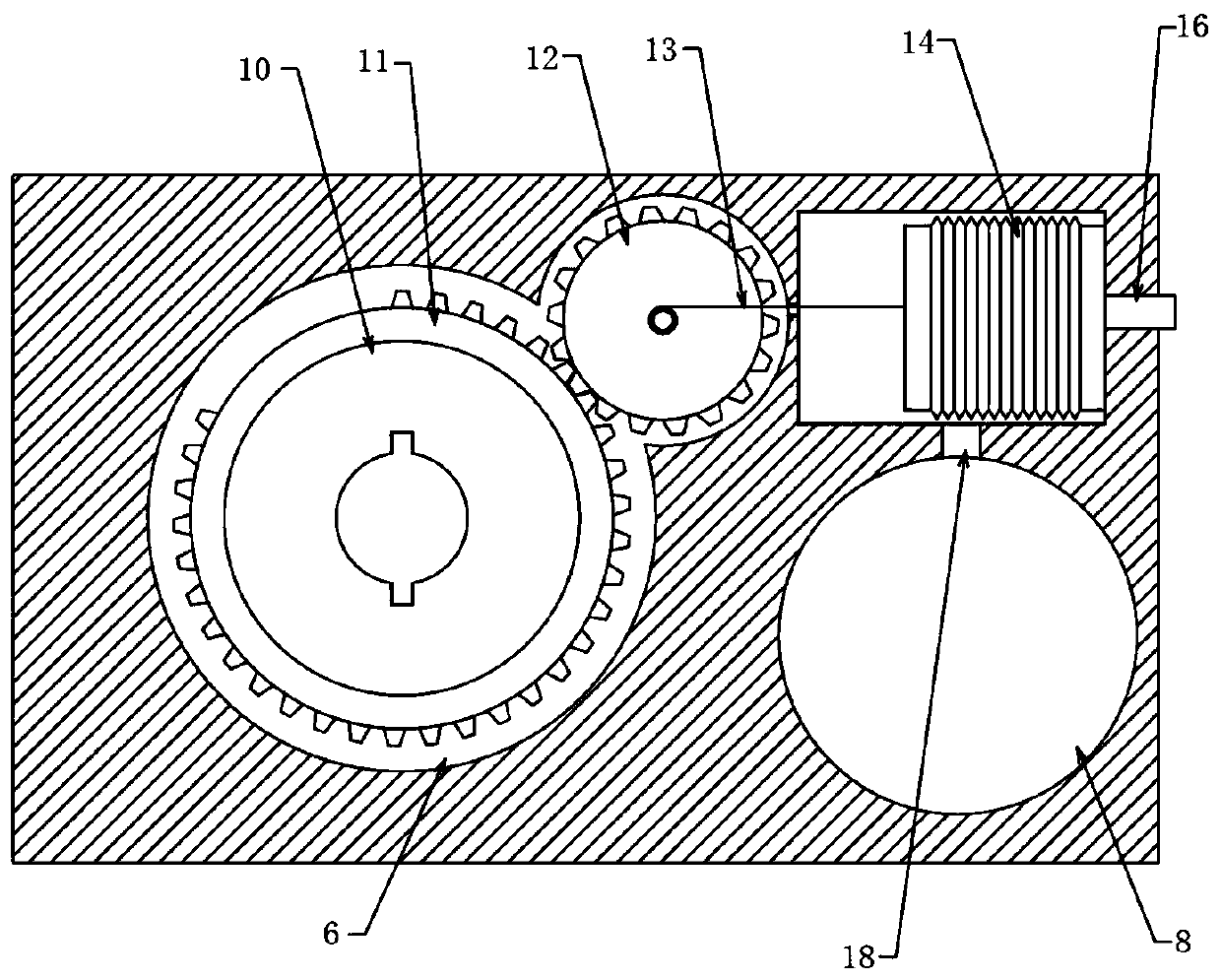
The invention discloses a thread taking device for bolt breakage. The thread taking device comprises a pair of fixing bases, wherein neodymium magnet attraction bases are fixedly installed at the bottoms of the fixing bases on the two sides, a shell is provided with a three-level coaxial cylindrical hole, an air bag groove and an oil storage groove, a shaft sleeve is fixedly inserted in an inner ring of a bearing, a traction rope is fixedly connected to a rotating shaft of a rotating gear, the end, away from the traction rope, of an extrusion air bag communicates with an air hole formed in theshell through a one-way air inlet valve, an air inlet channel is formed between the air bag groove and the oil storage groove, an oil outlet channel is formed in the bottom of the oil storage groove,a positioning groove is formed in the shaft sleeve, and a drill bit or a thread taking head is movably inserted into the positioning groove. According to the thread taking device for the bolt breakage, the drill bit and the thread taking head are positioned, the stability of the drill bit in the drilling process and the accuracy of the position are guaranteed, a loosening agent is injected into the inside along the hole wall while drilling is carried out, the loosening agent flows into the periphery of a broken bolt along the hole wall to loosen the bolt, the thread taking process is simplified, and the thread taking efficiency is improved.

Description

technical field [0001] The invention relates to the technical field of a broken wire device, in particular to a broken wire device for bolts. Background technique [0002] If the broken bolts of the fan unit are not found in time, the broken bolts will collide with other pitch system electronic components in the hub, resulting in unnecessary losses. At the same time, if the broken bolts are not replaced, other bolts next to the broken place will Increasing the load will bring huge hidden dangers to the normal operation of the fan unit for a long time, so it is necessary to remove the broken bolts in time to ensure the safe and stable operation of the unit. [0003] In the prior art, a device for extracting broken bolts from fan blades with the application number "CN201721012946.5" relates to the technical field of tools for extracting broken bolts, including drilling devices, extended drill pipes, drill bits, fixing plates and bolt extracting devices, fixing plates It can b...

Claims


Application Information

Patent Timeline
Patent Type & Authority Applications(China)
IPC IPC(8): B25B27/18
CPCB25B27/18
Inventor 刘东岐张小雷郎泽萌洪楠姚利陆畅赵海亮孟庆茂邹序昌葛小东
Owner 中广核(当涂)新能源有限公司
Learn More