
Optical module circuit and optical module

A technology of optical modules and circuits, applied in the field of optical modules, can solve the problems of normal operation of optical modules, product failure, etc.

Pending Publication Date: 2020-07-17
APAT OPTOELECTRONICS COMPONENTS
View PDF0 Cites 3 Cited by
  • Summary
  • Abstract
  • Description
  • Claims
  • Application Information

AI Technical Summary

Problems solved by technology

However, when performing over-current protection, the protection action is generally to control the optical module to stop working, which will affect the normal operation of the optical module, thus forming the impression that the product often fails in the mind of the customer. Therefore, when designing the optical module, It is necessary to avoid the overcurrent phenomenon of the APD as much as possible and reduce the number of triggers of the overcurrent protection

Method used


Image

  • Optical module circuit and optical module
  • Optical module circuit and optical module
  • Optical module circuit and optical module

Examples


Embodiment Construction

[0032] The technical solutions in the embodiments of the present invention will be clearly and completely described below in conjunction with the accompanying drawings in the embodiments of the present invention. If there are descriptions involving "first", "second", etc. The descriptions of "first", "second" and so on are for descriptive purposes only, and should not be understood as indicating or implying their relative importance or implying the number of indicated technical features. Thus, the features defined as "first" and "second" may explicitly or implicitly include at least one of these features.

[0033] The invention proposes an optical module circuit to reduce the trigger times of overcurrent protection, thereby improving the stability of the optical module.

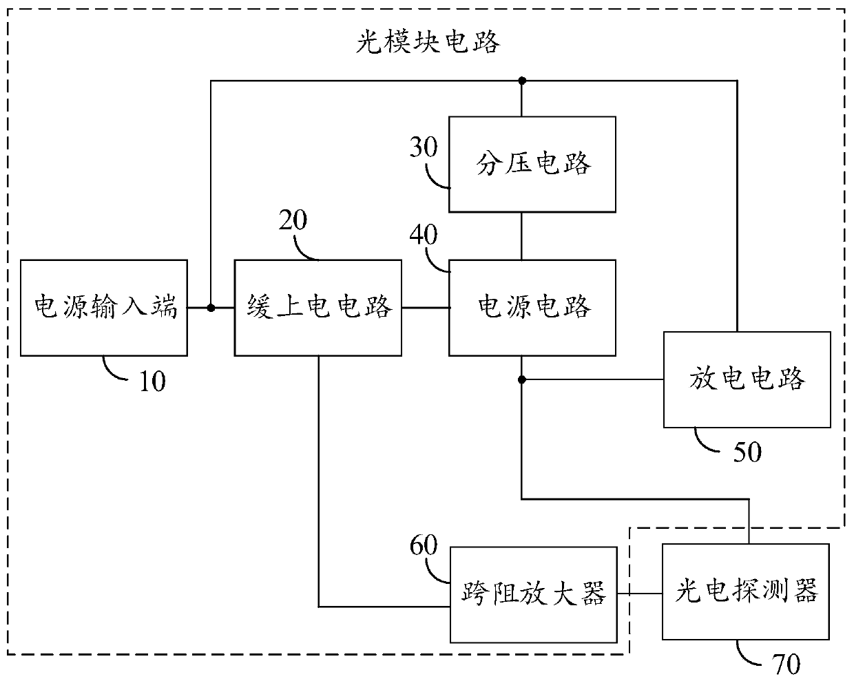
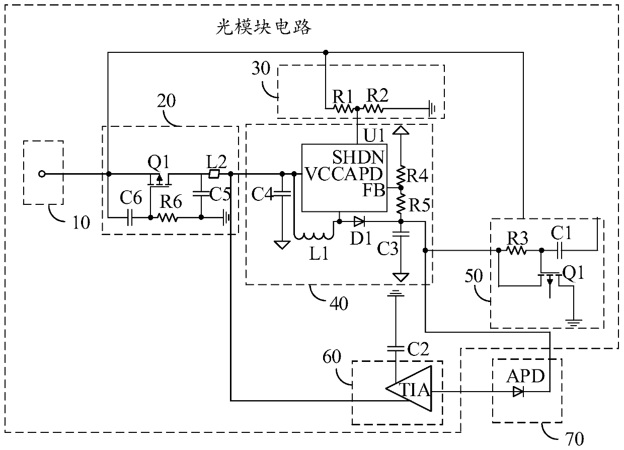
[0034] Such as figure 1 As shown, in an embodiment, the optical module circuit includes a power input terminal 10 , a transimpedance amplifier 60 , a power circuit 40 , a slow power-on circuit 20 , a voltage...


PUM


Abstract

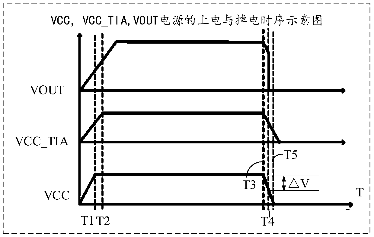
The invention discloses an optical module circuit and an optical module, the optical module circuit comprises a power supply input end, a transimpedance amplifier, a power supply circuit, a slow power-on circuit, a voltage division circuit and a discharge circuit, wherein the power supply circuit provides a working voltage for a photoelectric detector when a power supply voltage input by a power supply input end is greater than or equal to a first preset voltage value; the slow power-on circuit controls the trans-impedance amplifier to be powered on earlier than the photoelectric detector whenthe power supply voltage input by the power supply input end is greater than or equal to a first preset voltage value. When the power supply voltage input by the power supply input end is smaller than a first preset voltage value, the voltage division circuit divides the power supply voltage of the power supply circuit so as to accelerate the power-off speed of the power supply circuit. When thepower supply voltage input by the power supply input end of the discharge circuit is smaller than a first preset voltage value, the power supply circuit is powered off earlier than the trans-impedanceamplifier. The optical module circuit is used for reducing the triggering frequency of overcurrent protection.

Description

technical field [0001] The invention relates to the technical field of optical modules, in particular to optical module circuits and optical modules. Background technique [0002] In the current optical module design, the APD (avalanche diode) is designed with an overcurrent protection action to avoid damage to the optical module. However, when performing over-current protection, the protection action is generally to control the optical module to stop working, which will affect the normal operation of the optical module, thus forming the impression that the product often fails in the mind of the customer. Therefore, when designing the optical module, It is necessary to avoid the overcurrent phenomenon of the APD as much as possible, and reduce the number of triggering of the overcurrent protection. Contents of the invention [0003] The main purpose of the present invention is to provide an optical module circuit, aiming at reducing the triggering times of overcurrent pro...

Claims


Application Information

Patent Timeline
Patent Type & Authority Applications(China)
IPC IPC(8): H04B10/40H02M1/32H02M1/34
CPCH02M1/32H02M1/34H04B10/40H02M1/322
Inventor 庄礼杰王侃王彦伟
Owner APAT OPTOELECTRONICS COMPONENTS
Learn More