
Optical fiber mounting clamp suitable for flexible structure and using method thereof

A flexible structure and installation fixture technology, applied in the direction of optical fiber/cable installation, fiber mechanical structure, etc., can solve problems such as breakage, large deformation, excessive deformation of optical fiber, etc., to reduce stress and deformation, low cost, Ease of use

Pending Publication Date: 2020-07-17
TIANJIN RES INST FOR WATER TRANSPORT ENG M O T +1
View PDF0 Cites 2 Cited by
  • Summary
  • Abstract
  • Description
  • Claims
  • Application Information

AI Technical Summary

Problems solved by technology

In addition to the above-mentioned projects, optical fiber sensors can also be used in the deformation monitoring of flexible structures such as waterway soft rows. Unlike rigid structures, flexible structures are prone to large deformations during installation and laying. If the optical fiber and the flexible structure are completely fixed It will cause the optical fiber to deform too much with the flexible structure and break the phenomenon
At this stage, targeted optical fiber installation fixtures suitable for flexible structures have not yet appeared

Method used


Image

  • Optical fiber mounting clamp suitable for flexible structure and using method thereof
  • Optical fiber mounting clamp suitable for flexible structure and using method thereof
  • Optical fiber mounting clamp suitable for flexible structure and using method thereof

Examples


Embodiment Construction

[0019] In order to further understand the invention content, characteristics and effects of the present invention, the following examples are given, and detailed descriptions are as follows in conjunction with the accompanying drawings:

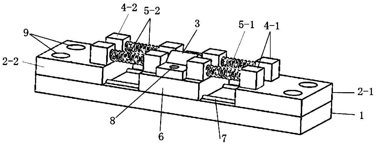
[0020] see Figure 1 ~ Figure 4 , an optical fiber installation fixture suitable for flexible structures, comprising a base 1, a front pressing piece 2-1 is provided at the front end of the base 1, and a rear pressing piece 2 is provided at the rear end of the base 1 -2.

[0021] Two sliding rails 7 parallel to each other and extending along the length direction of the base are fixedly connected between the front-end pressing piece 2-1 and the rear-end pressing piece 2-2, and a slider is installed on the sliding rail 7 6. The slider 6 is slidingly matched with the base 1 , and the fiber clamp 3 is fixedly installed on the slider 6 .

[0022] Two limit springs I5-1 symmetrically arranged at the front end of the slider 6 are arranged, and two...


PUM


Abstract

The invention discloses an optical fiber mounting clamp suitable for a flexible structure, which comprises a base. A front end pressing sheet is arranged at the front end of the base; a rear end pressing sheet is arranged at the rear end of the base; two sliding rails which are parallel to each other and extend along the length direction of the base are fixedly connected between the frontend pressing sheet and the rear end pressing sheet; a sliding block is mounted on the sliding rail; the sliding block is in sliding fit with the base, the optical fiber clamp is fixedly installed on the sliding block, two limiting springs I which are arranged in a bilateral symmetry mode are arranged at the front end of the sliding block, two limiting springs II which are arranged in a bilateral symmetry mode are arranged at the rear end of the sliding block, the limiting springs I are arranged between the frontend pressing piece and the sliding block, and the limiting springs II are arranged between the rear end pressing piece and the sliding block. The invention further discloses a using method of the clamp. The optical fiber can be prevented from being snapped when the monitored flexible structure generates large deformation, and the optical fiber can safely and stably monitor deformation data and damage conditions of the monitored flexible structure in real time.

Description

technical field [0001] The invention belongs to the field of hydraulic monitoring, in particular to an optical fiber installation fixture suitable for flexible structures and a use method thereof. Background technique [0002] At present, optical fiber sensing technology is widely used in engineering fields, such as tunnels, bridges, high-speed rail, ports, docks, housing construction, etc. In the above project, the optical fiber sensor needs to use a clamp to fix the optical fiber on the rigid structure, so that the optical fiber and the rigid structure can achieve the purpose of co-deformation. In addition to the above-mentioned projects, optical fiber sensors can also be used in the deformation monitoring of flexible structures such as waterway soft rows. Unlike rigid structures, flexible structures are prone to large deformations during installation and laying. If the optical fiber and the flexible structure are completely fixed The phenomenon that the optical fiber wil...

Claims


Application Information

Patent Timeline
Patent Type & Authority Applications(China)
IPC IPC(8): G02B6/46G02B6/44
CPCG02B6/46G02B6/44
Inventor 张国栋刘孟孟李俊位唐小龙王东方刘昌斌胡青也刘华张亚洲夏金志张勇王元骏田海天力向军郑超
Owner TIANJIN RES INST FOR WATER TRANSPORT ENG M O T
Learn More