Drainage device

A technology of drainage device and drainage pump, which is applied in the field of industrial manufacturing, can solve the problems that waste water cannot be automatically discharged by gravity, connected and discharged, etc.

Pending Publication Date: 2020-07-17
SUZHOU ZUOZHU HOT & COLD CONTROL TECH CO LTD
View PDF0 Cites 1 Cited by
  • Summary
  • Abstract
  • Description
  • Claims
  • Application Information

AI Technical Summary

Problems solved by technology

[0003] The high-altitude environmental simulation laboratory is used to truly simulate the high-altitude environment, and its internal air pressure must be lower than the external natural environmental pressure (usually atmospheric pressure). Due to the existence of pressure difference, the waste water in the high-altitude environmental simulation laboratory cannot naturally rely on gravity. discharge, and in order to ensure that the internal environment of the high-altitude environmental simulation laboratory is not affected by drainage (change the pressure), it is not possible to simply connect and discharge the waste water in the high-altitude environmental simulation laboratory directly into the external natural environment, so there is an urgent need for an automatic, uninterrupted Drainage equipment that has no effect on the indoor environment of the high-altitude environmental simulation test

Method used


Image

  • Drainage device
  • Drainage device
  • Drainage device

Examples


no. 1 example

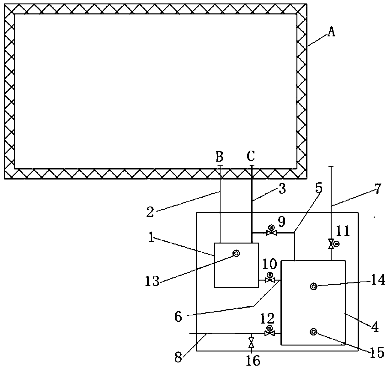
[0054] The first embodiment, such as figure 1 As shown, the drainage device provided by the present invention for draining water from a relatively low-pressure environment to a relatively high-pressure environment, for example, the environmental simulation test chamber simulates the plateau environment and its waste water is discharged to the external environment (atmospheric pressure), including:

[0055] The first water tank 1, which is a sealed box set in a relatively high-pressure environment, communicates with the relatively low-pressure environment through the first sealed pipeline 2 and the second sealed pipeline 3, the first sealed pipeline 2 is used for drainage, and the second sealed pipeline The second sealed pipeline 3 is used for pressure equalization;

[0056] The height of waste water outlet B in environmental simulation laboratory A is higher than the height of the first water tank 1, and the height of the first water tank 1 is higher than the height of the sec...


PUM


Abstract

The invention discloses a drainage device for draining water from a relatively low-pressure environment to a relatively high-pressure environment. The drainage device comprises a first water tank, a second water tank, a first electromagnetic valve, a second electromagnetic valve, a third electromagnetic valve, a fourth electromagnetic valve, a first liquid level meter, a second liquid level meterand a third liquid level meter, wherein the first water tank communicates with the low-pressure environment through a first sealing pipeline and a second sealing pipeline; the second water tank communicates with the second sealing pipeline through a third sealing pipeline, communicates with the first water tank through a fourth sealing pipeline and communicates with the relatively high-pressure environment through a fifth sealing pipeline and a sixth sealing pipeline; the first electromagnetic valve is arranged on the third sealing pipeline, the second electromagnetic valve is arranged on thefourth sealing pipeline, the third electromagnetic valve is arranged on the fifth sealing pipeline, and the fourth electromagnetic valve is arranged on the sixth sealing pipeline; and the first liquidlevel meter is installed in the first water tank, and the second liquid level meter and the third liquid level meter are installed in the second water tank. The drainage device can automatically andcontinuously drain the water from the relatively low-pressure environment to the relatively high-pressure environment.

Description

technical field [0001] The invention relates to the field of industrial manufacturing, in particular to a drainage device for draining water from a relatively low-pressure environment to a relatively high-pressure environment. Background technique [0002] At present, in order to improve the adaptability and reliability of products (including but not limited to automotive equipment), the products must be tested in various environmental conditions before leaving the factory, such as severe cold regions, hot summer regions, high altitude regions, etc. In order to save product development and testing time and reduce testing costs, many environmental condition simulation laboratories have been established, such as those used for high-altitude environment simulation. When conducting air-conditioning product tests, the high-altitude environment simulation laboratory has the need for wastewater discharge. In general, in order to verify the reliability of the product, the continuou...

Claims


Application Information

Patent Timeline
Patent Type & Authority Applications(China)
IPC IPC(8): F17D1/13F17D1/14F17D3/01F17D3/18F24F13/22G01M99/00
CPCF17D1/13F17D1/14F17D3/01F17D3/18F24F13/222G01M99/005
Inventor 张俊林
Owner SUZHOU ZUOZHU HOT & COLD CONTROL TECH CO LTD
Why Eureka
Try Eureka