
Sleeving combination equipment

A technology for equipment and capsules, which is applied in the directions of conveyor objects, drug delivery, capsule delivery, etc., can solve the problems of low capsule forming rate, low cutting efficiency, low feeding efficiency, etc., and achieves simple and stable positioning hole setting and principle. High efficiency and quality, stable capsule positioning effect

Pending Publication Date: 2020-07-17
XINCHANG HONGHAI MACHINERY
View PDF0 Cites 1 Cited by
  • Summary
  • Abstract
  • Description
  • Claims
  • Application Information

AI Technical Summary

Problems solved by technology

[0003] The cutting of capsules was initially cut by hand, which had defects such as low efficiency and unhygienic. After technical improvement, the current capsule cutting device appeared, which greatly improved the production efficiency and ensured that the production of capsules complied with the hygienic production standards of pharmaceuticals; , Capsule fitting was initially done by hand, which had defects such as low efficiency and unhygienic. After technical improvement, the current capsule fitting device appeared, which greatly improved production efficiency and ensured that the production of capsules complied with pharmaceutical hygiene. Production standards, the existing capsule equipment, still has the following defects: (1) The feeding device of the capsule is complicated to set, so that the feeding is slow and the feeding efficiency is low; (2) In the cutting device of the capsule, the cutting device of the capsule cannot Cutting is done in an inconsistent direction, resulting in low cutting efficiency; (3) In the capsule fitting device, the capsule is detached due to improper positioning, resulting in a low molding rate of capsule fitting
Through the capsule equipment of the prior art, the molding rate of the capsules obtained is low, and the product quality is relatively poor

Method used

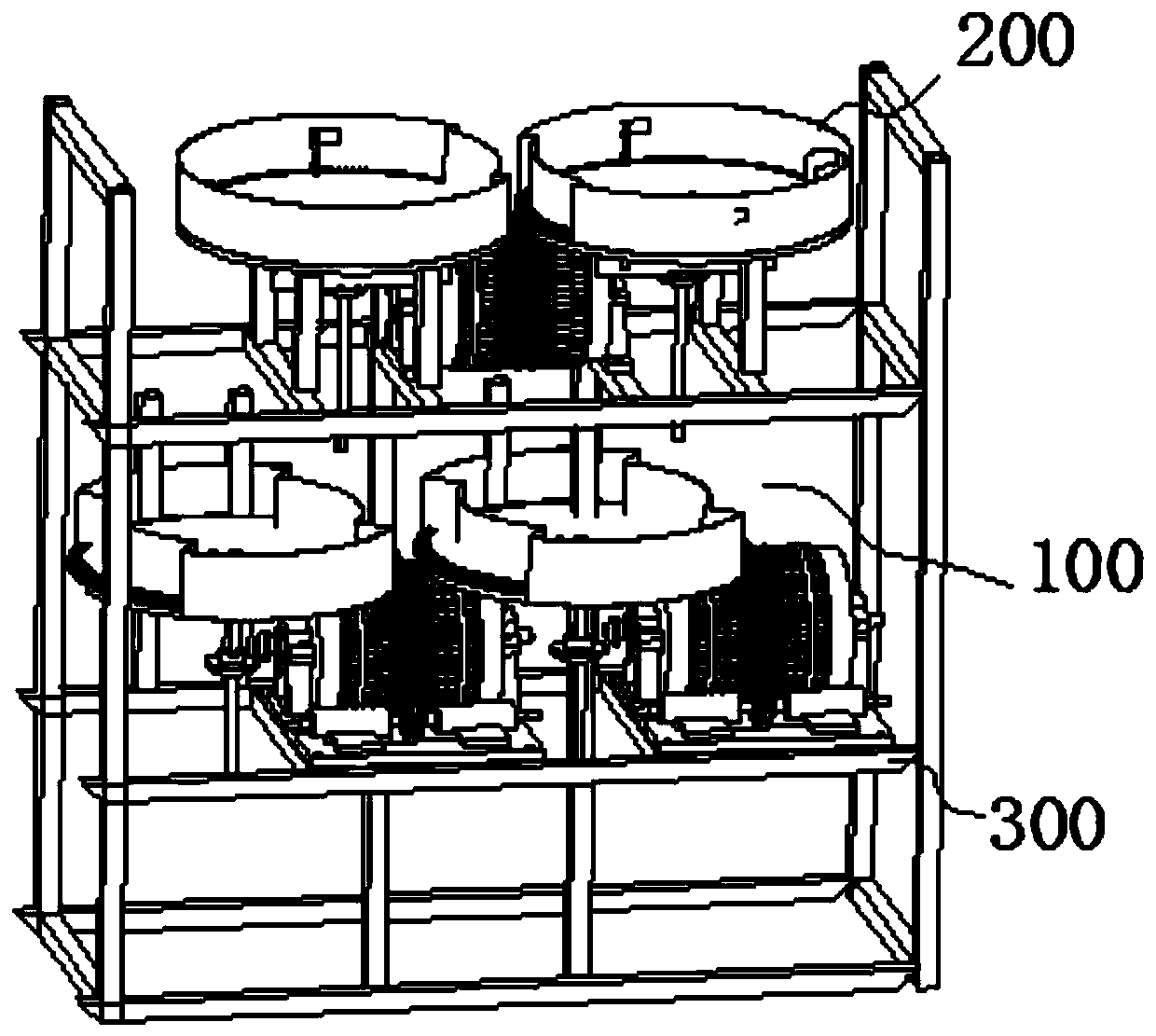
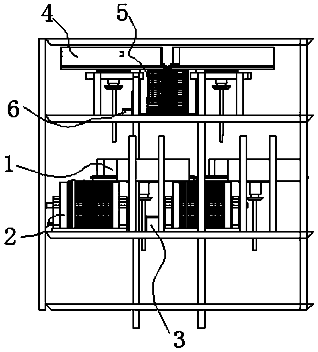
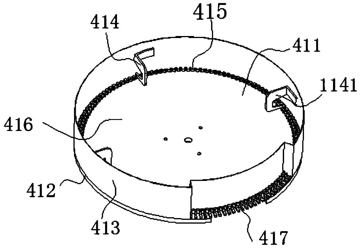

Image

  • Sleeving combination equipment
  • Sleeving combination equipment
  • Sleeving combination equipment

Examples


Embodiment Construction

[0080] In order to make the purpose, technical solutions and advantages of the embodiments of the present invention more clear, the following will clearly and completely describe the technical solutions of the embodiments of the present invention in conjunction with the drawings of the embodiments of the present invention. Apparently, the described embodiments are some, not all, embodiments of the present invention. Based on the described embodiments of the present invention, all other embodiments obtained by persons of ordinary skill in the art without creative efforts shall fall within the protection scope of the present invention.

[0081] In describing the present invention, it should be understood that the terms "center", "longitudinal", "transverse", "length", "width", "thickness", "upper", "lower", "front", " Orientation or position indicated by "back", "left", "right", "vertical", "horizontal", "top", "bottom", "inner", "outer", "clockwise", "counterclockwise", etc. T...


PUM


Abstract

The invention discloses sleeving combination equipment. The equipment comprises: a second feeding device, a sleeving combination device which is used for the sleeving combination of a first capsule and a second capsule, and a second driving device which is used for driving the second feeding device and / or the sleeving combination device to perform synchronous operation, wherein a plurality of second capsule feeding holes for placing capsules are distributed in the circumferential direction of the second feeding device, and the opening directions of the second capsule feeding holes are arrangedin the vertical direction. The sleeving combination equipment provided by the invention is simple in structure and good in sleeving combination forming rate, and the forming rate of obtained productsis extremely high.

Description

technical field [0001] The invention relates to equipment for producing capsules, in particular to a sleeved equipment. Background technique [0002] The preparation process of hollow capsules includes multiple processes: forming-cutting-fitting. After the capsules are formed, they usually have different lengths, and the ends need to be cut into uniform specifications by cutting equipment, and then A capsules and B capsules are combined by the fitting equipment The end capsules are made by fitting together. [0003] The cutting of capsules was initially cut by hand, which had defects such as low efficiency and unhygienic. After technical improvement, the current capsule cutting device appeared, which greatly improved the production efficiency and ensured that the production of capsules complied with the hygienic production standards of pharmaceuticals; , Capsule fitting was initially done by hand, which had defects such as low efficiency and unhygienic. After technical impr...

Claims


Application Information

Patent Timeline
Patent Type & Authority Applications(China)
IPC IPC(8): A61J3/07B29C65/56B29C65/78B29C69/00B65G47/24
CPCA61J3/077B29C65/56B29C65/78B29C69/001B65G47/24
Inventor 章国宏陈超刚
Owner XINCHANG HONGHAI MACHINERY
Learn More