
Visual puncture outfit

A puncture device and puncture rod technology, applied in puncture needles, medical science, catheters, etc., can solve the problems of easily blocking the camera angle of view, affecting the operation angle of view, and losing monitoring, so as to reduce the incidence of infection, improve surgical scenarios, reduce Effects of Trauma

Pending Publication Date: 2020-07-17
上海大博医疗科技有限公司
View PDF0 Cites 5 Cited by
  • Summary
  • Abstract
  • Description
  • Claims
  • Application Information

AI Technical Summary

Problems solved by technology

In the prior art, most trocars are not equipped with cameras and searchlights, and a laparoscope (optical test tube) is used to meet the monitoring requirements. For example, after the laparoscope is withdrawn, the monitoring in the abdominal cavity will inevitably be lost, and there are certain safety hazards
Or the camera and searchlight of other technical trocars are set on the puncture rod to observe the position and status of the puncture in real time. However, after the puncture is completed and the puncture rod is taken out, the medical staff need to assist in observing the follow-up operation through the laparoscope. Thus it is impossible to reduce the puncture hole and achieve the purpose of reducing the wound
There is a type of puncture device whose camera is set on the outer sheath tube. After taking out the puncture rod, the internal conditions can be observed in real time, but because the camera is fixed on the outer sheath tube wall, when the instrument enters, it is easy to block the viewing angle of the camera and affect the operation. angle of view

Method used


Image

  • Visual puncture outfit
  • Visual puncture outfit
  • Visual puncture outfit

Examples


Embodiment 1

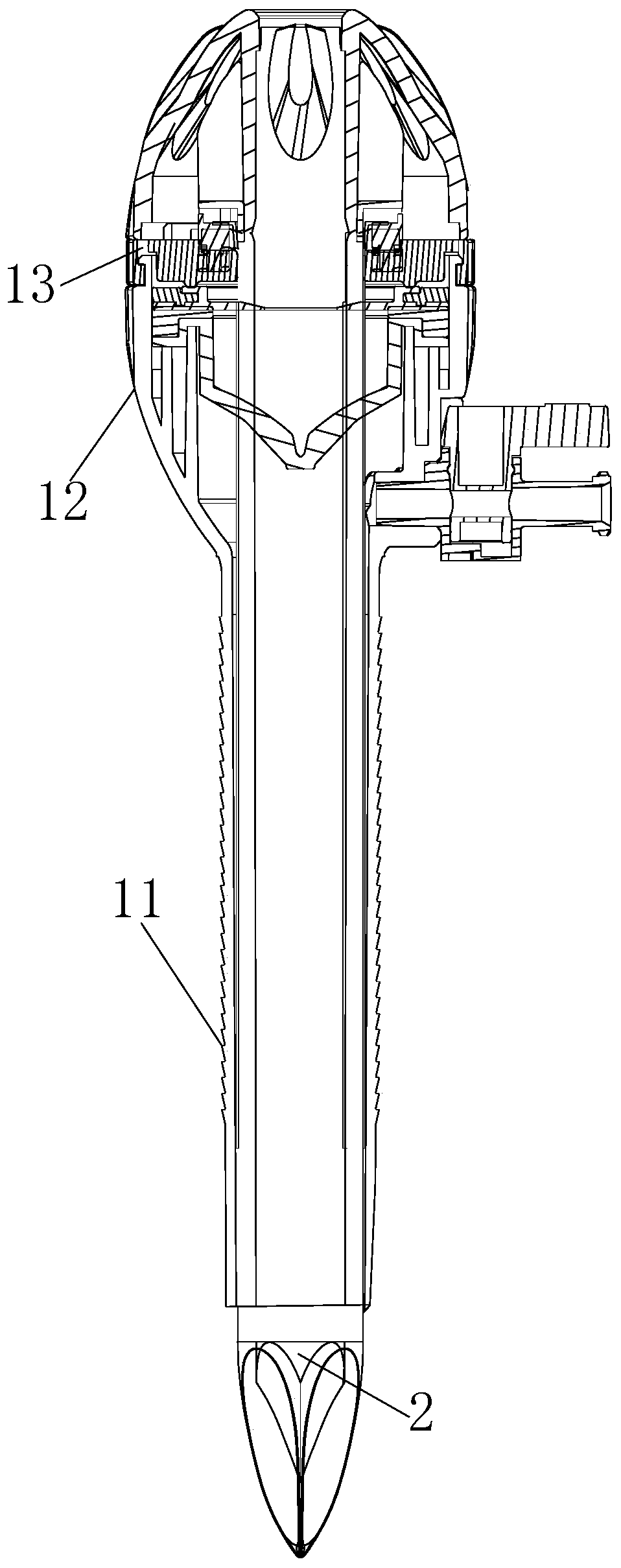
[0029] Such as Figure 1 to Figure 14 Shown is a schematic diagram of an embodiment of a visual puncture device provided by the present invention.

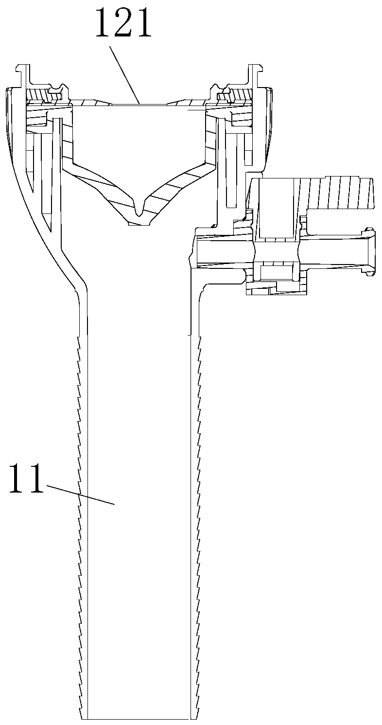
[0030] The visible puncturer includes a sheath assembly, a puncture rod 2 and a camera assembly 3; the sheath assembly includes an outer sheath 11 that penetrates up and down, and the puncture rod 2 is placed in the passage of the outer sheath 11; The camera assembly 3 is placed in the passage of the outer sheath 11 and can be rotated in the passage of the outer sheath 11 .

[0031] The sheath tube assembly also includes a sheath tube seat 12 arranged at the upper end of the outer sheath tube 11, the sheath tube seat 12 is provided with a through hole A121 communicating with the outer sheath tube 11, and the puncture rod 2 and the camera assembly 3 pass through The through hole A121 of the sheath tube seat 12 enters the passage of the outer sheath tube 11 .

[0032] The camera assembly 3 includes a rotating shaft 31, a base 32 c...

Embodiment 2

[0051] Embodiment two: if Figure 15 to Figure 17 What is shown is a schematic diagram of an embodiment of another visual puncture device provided by the present invention. The structure of the second embodiment is basically the same as that of the first embodiment, the main difference is that the connection relationship between the rotating shaft 31 and the control member is different, and the second embodiment does not include an adjustment unit for sliding the base 32 in the longitudinal direction.

[0052] In the second embodiment, the control member is a connecting shaft 39, and the guide hole 131 is a circular hole that allows the connecting shaft 39 to pass through; the left end of the connecting shaft 39 is provided with a gear A391, and the rotating shaft 31 The upper end is provided with a gear B40 that meshes vertically with the gear A391, and the connecting shaft 39 is rotated with the central axis of the connecting shaft 39 as the rotating shaft, which drives the ...


PUM


Abstract

The invention relates to a visual puncture outfit. The visual puncture outfit comprises a sheath tube assembly, a puncture rod and a camera assembly, wherein the sheath tube assembly comprises an outer sheath tube which is through from top to bottom; the puncture rod is arranged in a passage of the outer sheath tube; the camera assembly is arranged in the passage of the outer sheath tube and can rotate by a certain angle in the passage of the outer sheath tube. The visual puncture outfit can be used for establishing an operation channel, and the camera assembly of the visual puncture outfit not only can rotate by a certain angle in the horizontal direction but also can move along the longitudinal direction, so that the visual puncture outfit can be used to observe an operation scene at anytime and adjust a shooting angle at any time according to actual requirements, and thus operation can be carried out better.

Description

technical field [0001] The invention relates to a visual puncture device. Background technique [0002] The puncture device is an essential instrument for establishing a surgical channel and an observation channel in abdominal surgery. The trocar usually includes an outer sheath serving as an access channel for other surgical instruments and a puncture rod penetrating through the outer sheath. First, in order to penetrate the skin, cut the epidermis of the skin with a scalpel, then use the puncture rod to penetrate the skin and enter the body cavity together with the outer sheath, then pull out the puncture rod, and the outer sheath can be used to introduce various instruments and tools passage in the abdominal cavity. In the prior art, most trocars are not equipped with cameras and searchlights, and use a laparoscope (optical test tube) to meet the monitoring requirements. If the laparoscope is withdrawn, the monitoring in the abdominal cavity will inevitably be lost, and...

Claims


Application Information

Patent Timeline
Patent Type & Authority Applications(China)
IPC IPC(8): A61B17/34A61B90/00
CPCA61B17/3415A61B90/361A61B90/37
Inventor 莫易凡林志雄林聪杰胡林锋廖振源
Owner 上海大博医疗科技有限公司
Learn More