Air sample collecting device

A sample collection and air technology, applied in the direction of sampling devices, measuring devices, electric operating devices, etc., can solve the problems of air particle number deviation, increased labor costs, waste of time, etc.

Inactive Publication Date: 2020-07-14
朱晓艳
View PDF12 Cites 0 Cited by
  • Summary
  • Abstract
  • Description
  • Claims
  • Application Information

AI Technical Summary

Problems solved by technology

[0002] In order to detect the environment around pesticide factories, food manufacturing plants, hospitals and specific areas, it is necessary to use equipment to collect particles in the air into collection bottles with liquid, and blow air into the collection bottles for a long time to make the air The particles in the liquid are dissolved in the liquid, and finally the particles in the liquid are analyzed. The following deficiencies exist in the collection of air samples through the existing equipment: 1. There is a deviation in the number of particles in the air in the three time periods of the morning, middle and evening. Only by random One-time air collection is easy to cause large errors in the experimental results
2. It takes a long time to collect air samples each time, and manual continuous operation is required during collection, and the collection work is extremely time-consuming
3. When the existing equipment collects air samples, the equipment needs to be set up in the area to be tested, and then the collection starts. When the collection of one collection bottle is completed, the next collection bottle needs to be replaced manually. The manual replacement is inefficient and additional labor cost

Method used


Image

  • Air sample collecting device
  • Air sample collecting device
  • Air sample collecting device

Examples


Embodiment Construction

[0025] In order to better understand the present invention, the implementation manner of the present invention will be explained in detail below in conjunction with the accompanying drawings.

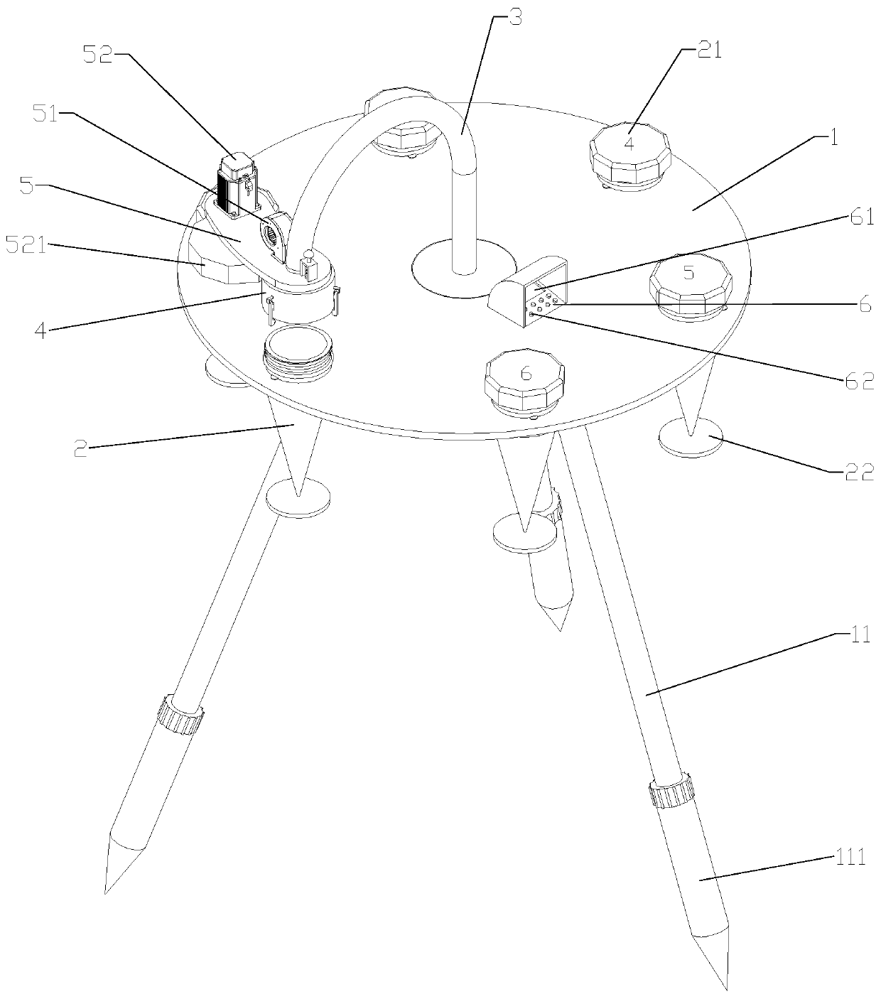
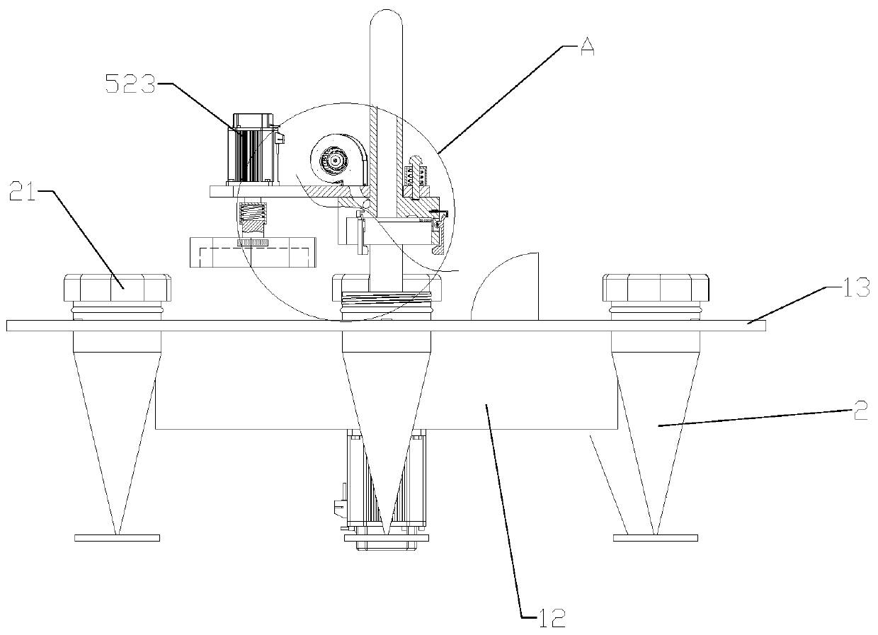
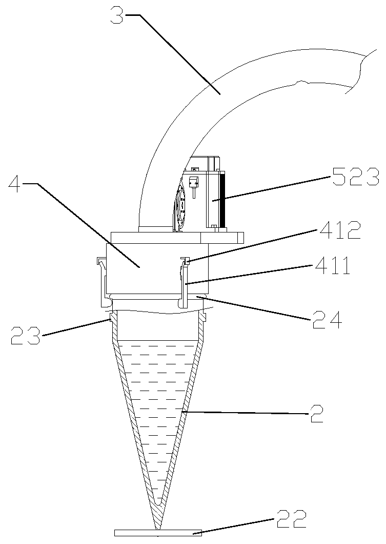
[0026] as attached figure 1 to attach Figure 9 The shown air sample collection device includes a frame 1, on which a plurality of through holes 131 are arranged at equal intervals around the circumference, and a collection bottle 2 with a tapered cavity inside is placed in each through hole 131. The specific implementation is as follows: the bottom end of the frame 1 is a cylinder 12 , and the top end is a flat plate 13 with a through hole 131 . A limiting block 23 is provided on the side wall of the collection bottle 2 , and a card slot 131 a is provided on the side wall of the through hole 131 of the plate 13 . When in use, it is enough to insert the conical collection bottle 2 into the through hole 131 of the plate 13 . The upper end of each collection bottle 2 is threadedly conn...


PUM


Abstract

The invention discloses an air sample collecting device which comprises a rack, and a plurality of conical collecting bottles containing liquid detachably connected to the rack at equal intervals in the circumferential direction. A plurality of supporting legs are hinged to the bottom end of the rack, a center rod is rotatably arranged in the middle of the rack, the bottom end of the center rod isconnected with a center rod driving mechanism for driving the center rod to ascend, descend and rotate, and the top end of the center rod extends to the position above the collecting bottle and is connected with a blocking cover capable of blocking an opening in the upper end of the collecting bottle. A connecting mechanism connected with the collecting bottle is arranged on the plugging cover; an arc-shaped supporting plate is rotatably arranged on the center rod at the top end of the plugging cover; and a fan, a bottle cover opening device and a supporting plate limiting mechanism are arranged on the supporting plate. The bottle cap opening device comprises an opening head which is arranged at the bottom end of the supporting plate, matched with the bottle cap and provided with a polygonal groove. The device has the characteristics of automatically replacing the collecting bottle, collecting the air sample at regular time and being convenient to take.

Description

technical field [0001] The present invention relates to air sample collection devices. Background technique [0002] In order to detect the environment around pesticide factories, food manufacturing plants, hospitals and specific areas, it is necessary to use equipment to collect particles in the air into collection bottles with liquid, and blow air into the collection bottles for a long time to make the air The particles in the liquid are dissolved in the liquid, and finally the particles in the liquid are analyzed. The following deficiencies exist in the collection of air samples through the existing equipment: 1. There is a deviation in the number of particles in the air in the three time periods of the morning, middle and evening. Only by random One-time air collection is likely to cause large errors in the experimental results. 2. It takes a long time to collect air samples each time, and manual continuous operation is required during collection, and the collection wor...

Claims


Application Information

Patent Timeline
IPC IPC(8): G01N1/22B67B3/20B67B7/18
CPCG01N1/2273B67B3/20B67B7/182
Inventor 朱晓艳佟海波
Owner 朱晓艳
Why Eureka
Try Eureka