
Multi-millimeter-wave radar combined self-calibration method and system

A millimeter-wave radar and joint calibration technology, which is applied to radio wave measurement systems and instruments, can solve problems affecting production line progress, low precision, and large equipment investment, so as to save labor costs, improve production efficiency, and ensure safety. Effect

Inactive Publication Date: 2020-07-10
DONGFENG MOTOR CORP HUBEI
View PDF8 Cites 4 Cited by
  • Summary
  • Abstract
  • Description
  • Claims
  • Application Information

AI Technical Summary

Problems solved by technology

Traditionally, the angle Doppler generator is used for correction, which requires a large investment in equipment and affects the progress of the production line
[0003] Due to the large number of car parts, millimeter-wave radar installed on the car will inevitably have unpredictable errors, which will affect the deviation between the system's perception of the target position and the actual position.
In order to eliminate this deviation, most manufacturers set up angle calibration equipment on the production line and set up angle calibration posts. This method requires labor, and the calibration process is cumbersome and affects production efficiency.
[0004] In addition, the current self-calibration method has more restrictions on the use environment, and the calibration is limited to the self-calibration of single millimeter wave radar, lack of joint calibration solutions, cannot correct and learn from each other, and has the problem of low accuracy
At the same time, the current self-calibration process must find a straight strong reflector for calibration, and the length requirement is high (such as high-speed kilometers guardrail), some 4S shops and factories do not have this condition

Method used


Image

  • Multi-millimeter-wave radar combined self-calibration method and system
  • Multi-millimeter-wave radar combined self-calibration method and system
  • Multi-millimeter-wave radar combined self-calibration method and system

Examples


Embodiment Construction

[0041] The present invention will be further described in detail below with reference to the accompanying drawings and specific embodiments, so as to facilitate a clear understanding of the present invention, but they do not limit the present invention.

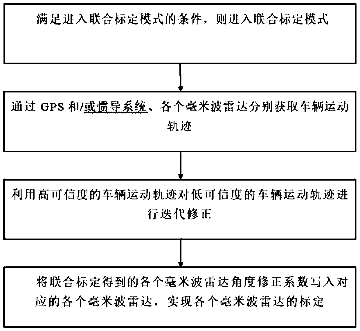
[0042] like figure 1 As shown, a multi-millimeter-wave radar joint self-calibration method of the present invention, its process is as follows:

[0043] Install multiple millimeter-wave radars on the vehicle, and the methods for joint self-calibration of multiple millimeter-wave radars include:

[0044] Determine whether the vehicle meets the conditions for entering the calibration mode, and if the conditions are met, enter the calibration mode;

[0045] Obtain vehicle motion trajectories through GPS and / or inertial navigation system and various millimeter-wave radars respectively;

[0046] Iteratively corrects the low-confidence vehicle trajectory by using the high-confidence vehicle trajectory until the credibility of the...


PUM


Abstract

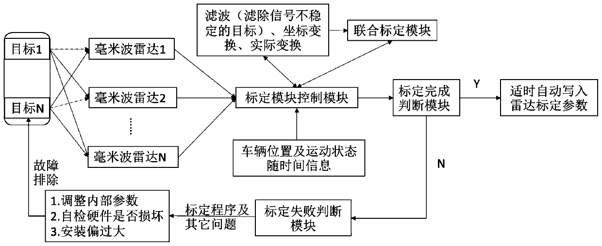
The invention relates to the technical field of automotive electronics, in particular to a multi-millimeter-wave radar combined self-calibration method and system. The method comprises the steps thatmultiple millimeter-wave radars are installed on a vehicle, whether the vehicle meets the condition of entering a calibration mode or not is judged, and if yes, the calibration mode is entered; each millimeter wave radar obtains a vehicle motion track through a GPS and / or inertial navigation system; the low-credibility vehicle motion trail is iteratively corrected by using the high-credibility vehicle motion trail until the credibility of the vehicle motion trail obtained by the GPS and / or inertial navigation system and each millimeter-wave radar reaches a set credibility range, and the combined calibration is ended; and each millimeter wave radar angle correction coefficient obtained by combined calibration is written into each corresponding millimeter wave radar to realize calibration ofeach millimeter wave radar. Iterative correction is carried out through combination of multiple motion trails and credibility in the combined calibration mode so that the calibration precision is higher.

Description

technical field [0001] The invention relates to the technical field of automotive electronics, in particular to a multi-millimeter wave radar joint self-calibration method and system. Background technique [0002] Millimeter-wave radar is integrated into the vehicle environment, and there will be an installation angle error. At present, the radar can support a detection distance of 100 meters, and the 1° error is 1.75m at a distance of 100mm. It is easy to misjudge the lane of the target vehicle and the height of the obstacles in front. All need to go through the calibration process. Traditionally, the correction is performed by an angular Doppler generator, which requires a large investment in equipment and affects the progress of the production line. [0003] Due to the large number of components that make up the car, the millimeter-wave radar installed on the car will inevitably have unpredictable errors, which will affect the system's perception of the deviation betwee...

Claims


Application Information

Patent Timeline
Patent Type & Authority Applications(China)
IPC IPC(8): G01S7/40
CPCG01S7/4004
Inventor 刘春华李明虎刘千韦胡华军卢鹏飞
Owner DONGFENG MOTOR CORP HUBEI
Learn More