Portable swing angle testing device for automobile windscreen wiper

A test device and a portable technology, applied in the field of portable swing angle test devices, can solve problems such as the inconvenience of developing and loading wiper products, the inability to test R&D products in time, and the inability to test the wiper swing angle, so as to ensure the progress of research and development, Simple structure and good consistency

Pending Publication Date: 2020-07-10
成都华川电装有限责任公司
View PDF0 Cites 2 Cited by
  • Summary
  • Abstract
  • Description
  • Claims
  • Application Information

AI Technical Summary

Problems solved by technology

However, because the test bench cannot be moved by the way, when it is necessary to analyze whether the swing angle of the wiper meets the design requirements during the experiment of the wiper product or the loading process of the OEM, the wiper in the laboratory or the OEM can only be removed at present. Then take it to the special test bench in the production workshop for testing
The test of the wiper swing angle is cumbersome, time-consuming and laborious, which brings great inconvenience to the development and loading of wiper products, affects the production progress, and reduces the efficiency
Moreover, due to the different installation dimensions of wiper blades, special test tooling is used to test the swing angle of wiper blades at present, and the manufacturing cycle of test tooling is relatively long. Therefore, after the initial development of wiper products, often due to It is impossible to test the swing angle of the wiper before it is manufactured, and the unqualified R&D products cannot be tested in time, which seriously affects the R&D progress

Method used


Image

  • Portable swing angle testing device for automobile windscreen wiper
  • Portable swing angle testing device for automobile windscreen wiper
  • Portable swing angle testing device for automobile windscreen wiper

Examples


Embodiment Construction

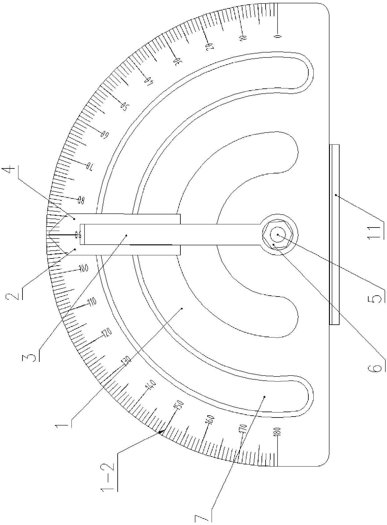
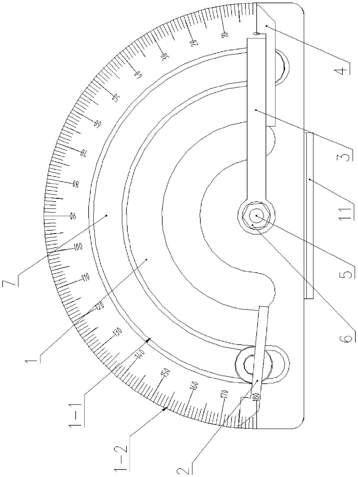
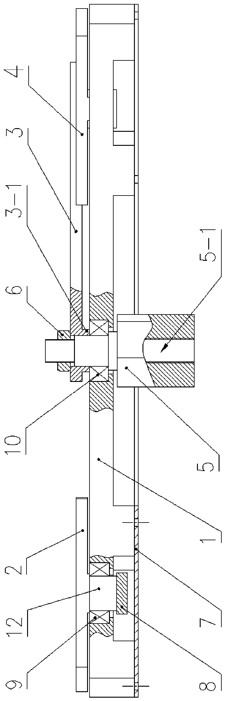
[0033] see Figure 1 to Figure 8, a portable swing angle testing device for an automobile wiper, comprising a dial 1, and a fixing base 11 for fixing the dial 1 is arranged at the lower end of the dial 1 . The upper end of the fixed base 11 is provided with a detent 11-1 for preventing the dial 1 from rotating. The detent 11-1 is located at the upper end of the side wall of the fixed base 11 and extends upward. The detent 11-1 is against the scale. The linear side wall of the disc 1 forms a limit. The anti-rotation part 11-1 restricts the rotation of the dial 1, which can improve the accuracy of test results. The dial 1 is provided with a guide groove 1-1 in the shape of a superior arc, and along the extending direction of the guide groove 1-1, an angle marking line 1-2 is provided, and the angle marking line 1-2 is 0-180 degrees. The side wall of the dial 1 located outside the guide groove 1-1 is in the shape of a semicircle. The dial 1 is located at the center of the guid...


PUM


Abstract

The invention discloses a portable swing angle testing device for an automobile windscreen wiper. The portable swing angle testing device comprises a dial. A fixing base for fixing the dial is arranged at the lower end of the dial; the dial is provided with a major arc-shaped guide groove, angle scribed lines are arranged in the extending direction of the guide groove; the dial is provided with ashaft hole at the circle center of the guide groove; a rotating shaft connected with a windscreen wiper rotating shaft is in sliding fit with the shaft hole; a poke rod is fixedly connected on the upper end of the rotating shaft; a left pointer and a right pointer are arranged on the left side and the right side of the free end of the poke rod respectively. Cylinders extending downwards are arranged on the left pointer and the right pointer; the cylinders are in sliding fit in the guide groove through rollers; a magnet block is fixed to the lower end face of each cylinder, a bottom plate madeof ferromagnetic materials is fixed to the lower end of the dial guide groove, a gap is reserved between the bottom plate and the magnet blocks, the opposite faces of the left pointer and the right pointer are indication edges, and the indication edges and the central axis of the poke rod are located on the same straight line.

Description

technical field [0001] The invention relates to the technical field of automobile wipers, in particular to a portable swing angle testing device for automobile wipers. Background technique [0002] The car wiper is a device used to brush or scrape off the raindrops and dust attached to the windshield, which is used to improve the visibility of the driver and increase driving safety. After the car wiper is produced, it is necessary to test the swing angle of the wiper to check whether the wiping range of the wiper arm meets the requirements. At present, the test of the wiper swing angle is carried out on the swing angle test bench dedicated to the wiper production workshop. However, because the test bench cannot be moved by the way, when it is necessary to analyze whether the swing angle of the wiper meets the design requirements during the experiment of the wiper product or the loading process of the OEM, the wiper in the laboratory or the OEM can only be removed at present...

Claims


Application Information

Patent Timeline
Patent Type & Authority Applications(China)
IPC IPC(8): G01M13/00G01M17/007G01B5/24
CPCG01B5/24G01M13/00G01M17/007
Inventor 杜树浩朱攀
Owner 成都华川电装有限责任公司
Why Eureka
Try Eureka