


Quick Research
Generate reliable direction feasibility study reports for your R&D in just a few steps.

Technical Q&A
Discover and master advanced knowledge NOW. Basics, ideas, possibilities, all at once.

Find Solutions
As an expert in R&D theories, this can generate solutions to your technical problems instantly.

Evaluate Feasibility
Analyze your overall solution with one click, know your potential R&D risks in advance.

Monitor Landscape
Get weekly tech updates, stay abreast of the latest tech innovations and key insights.
Self-guiding wireless charger and working method thereof
A technology of wireless chargers and working methods, which can be applied to current collectors, electric vehicles, electrical components, etc., and can solve problems such as inability to charge
- Summary
- Abstract
- Description
- Claims
- Application Information
AI Technical Summary
Problems solved by technology
Method used
Image

Examples
Embodiment 1
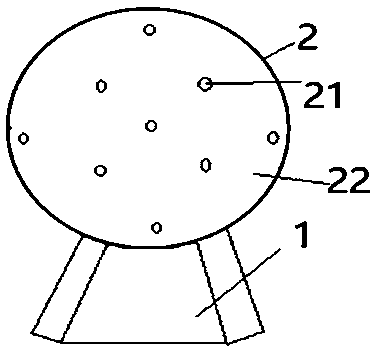
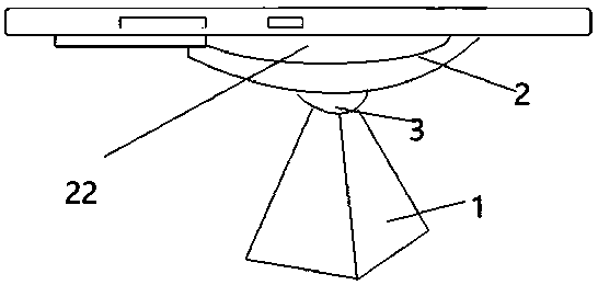
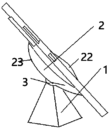
[0065] as attached figure 1 , attached figure 2 , attached image 3 and Figure 4 As shown, a self-guided wireless charger in the present invention includes: a base 1 and a launch pad 2, and the base 1 and the launch pad 2 are connected through a transmission device 3;
[0066] as attached figure 1 As shown, the transmitting plate 2 is provided with a sensor array 21, and the sensor array 21 is used to obtain the outer frame of the mobile phone to be charged and the position of the wireless receiving coil;
[0067] as attached Figure 4 As shown, the base 1 is provided with a control module 11, the control module 11 is connected to the sensor array 21, and the control module 11 controls the transmission according to the outer frame of the mobile phone to be charged and the position of the wireless receiving coil. The device corrects the position of the launching plate 2, and aligns the launching plate 2 with the mobile phone to be charged.
[0068] The principle of the ...
Embodiment 2
[0071] As an embodiment of the present invention: as attached Figure 4 As shown, the control module 11 includes a control chip 110, a resonant circuit 111 and a driver 112; wherein,
[0072] The control chip 110 is connected to the sensor array 21;
[0073] The control chip 110 is connected to the resonant circuit 111 and the driver 112 respectively;
[0074] The resonant circuit 111 and the driver 112 are respectively connected to the launch pad 2;
[0075] The resonant circuit 111 is electrically connected to the driver 112;
[0076] The resonant circuit 111 is composed of an inductance L, a capacitor C and a transmitting coil F connected in series, wherein. as attached Figure 4 As shown, in one embodiment, the output terminal of the inductor L, the input terminal of the emitting coil and the input terminal of the capacitor C are all connected to the voltage stabilizing resistor R.
[0077] The principle of the present invention is: the control chip 110 of the control...
Embodiment 3
[0080] As an embodiment of the present invention: the launch disk 2 is made of magnetic material; wherein,
[0081] The magnetic material includes ferrite or nanocrystals.
[0082] Both magnetic oxide and nanocrystals are magnetic materials, which can make the mobile phone fixed on the launch pad, and then realize the non-interference between charging and playing the mobile phone through the transmission device 3 .
PUM
 Abstract
Description
Claims
Application Information
 - R&D Engineer
- R&D Manager
- IP Professional
- Industry Leading Data Capabilities
- Powerful AI technology
- Patent DNA Extraction
Browse by: Latest US Patents, China's latest patents, Technical Efficacy Thesaurus, Application Domain, Technology Topic, Popular Technical Reports.
© 2024 PatSnap. All rights reserved.Legal|Privacy policy|Modern Slavery Act Transparency Statement|Sitemap|About US| Contact US: help@patsnap.com