Wind power blade and fan
A technology for wind power blades and blade bodies, which is applied in the field of wind power generation and can solve the problems of weak connection of flexible bending parts and the like
- Summary
- Abstract
- Description
- Claims
- Application Information
AI Technical Summary
Problems solved by technology
Method used
Image

Examples
no. 1 approach
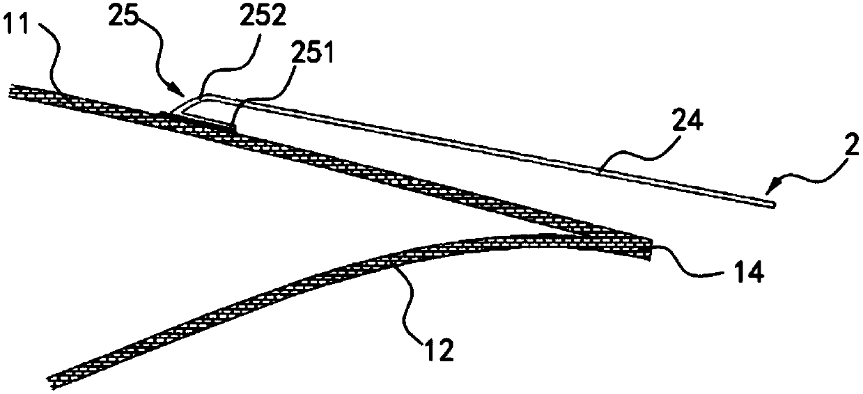
[0058] The present invention provides a wind turbine blade, which includes a blade body 1 and a flexible extension 2. The blade body 1 includes a suction surface 11 and a pressure surface 12, a front edge 13 and a rear edge 14. The flexible extension 2 includes a first end 21 and a second end 22. The first end 21 has a bending portion 25 connected to the suction surface 11, and the second end 22 is freely directed toward the blade body 1 The trailing edge 14 extends.
[0059] When the wind power blade is working, the flexible extension 2 can be passively deformed, thereby changing the trailing edge side airfoil of the wind power blade. Among them, the term “passive deformation” refers to the influence or action of some external force, the flexible extension part 2 swings toward or away from the suction surface 11 with its connection with the suction surface 11 as an axis. In addition, it should be understood that the external force may be generated by aerodynamics, gravity and / ...
no. 2 approach
[0086] The second embodiment is a schematic modification of the first embodiment, and the same technical features as those of the first embodiment will not be described in detail here. The differences are:
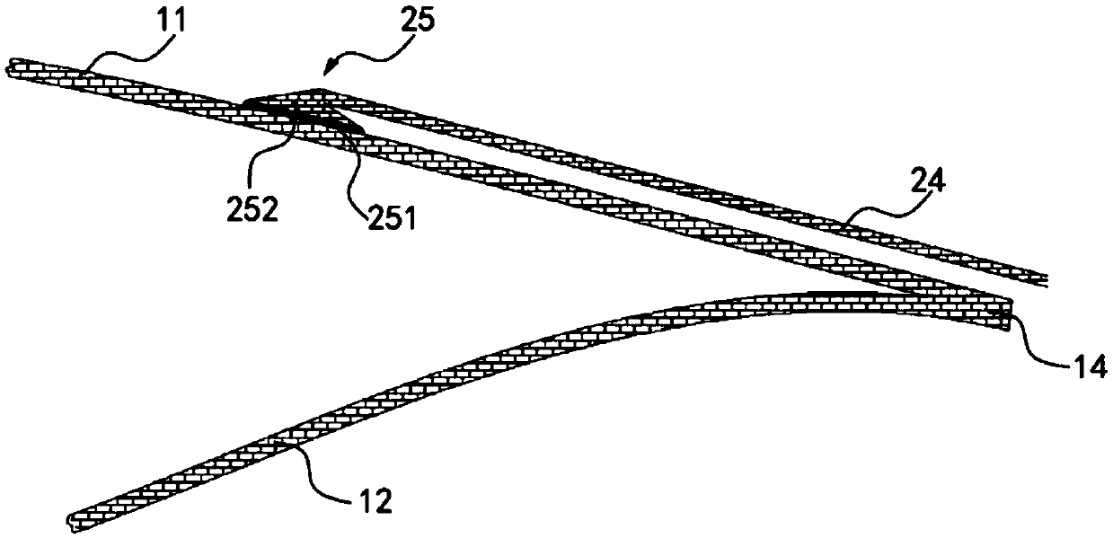
[0087] Such as figure 2 As shown, the bending portion 25 includes a connecting portion 252. One end of the connecting portion 252 starts from the end surface of the folded edge 251 facing the front edge 13 and extends along the suction surface 11 to the front edge 13, and the connecting portion 252 faces the blade body 1 One side of the front edge 13 forms an inclined surface, and the connecting portion 252 is connected to the suction surface 11. In other words, the cross-sectional shape of the bent portion 25 along the chord direction D may be approximately a triangle, and the end of the extension portion body close to the front edge 13 is integrally formed on the top of the triangle. Accordingly, the connecting portion 252 and the folded edge 251 are simultaneously connect...
no. 3 approach
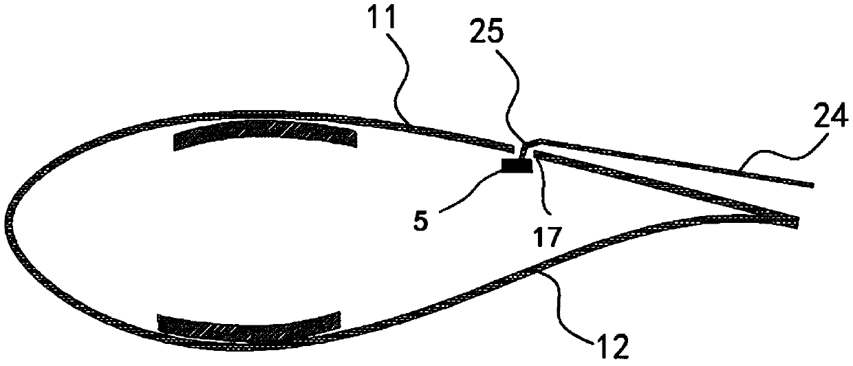
[0089] Such as image 3 As shown, in this embodiment, the flexible extension portion 2 includes an extension portion body 24 and a bending portion 25. The bending portion 25 is provided at one end of the extension portion body 24 facing the front edge 13 of the blade body 1, and the suction surface 11 has The opening 17 and the bent portion 25 can be fitted into the opening 17.
[0090] It should be understood that one end of the bent portion 25 may be connected to the extension body 24, and the other end of the bent portion 25 may extend toward the suction surface, and the extension direction may be perpendicular to the suction surface, or It is an acute or obtuse angle with the suction surface.
[0091] In addition, in this embodiment, the number of openings 17 is not limited, and it may be one, two or more, and a plurality of openings 17 may be arranged at intervals. The shape of the opening 17 may be rectangular, hole-shaped or other shapes. When the number of openings 17 is ...
PUM
 Abstract
Description
Claims
Application Information
 - R&D
- Intellectual Property
- Life Sciences
- Materials
- Tech Scout
- Unparalleled Data Quality
- Higher Quality Content
- 60% Fewer Hallucinations
Browse by: Latest US Patents, China's latest patents, Technical Efficacy Thesaurus, Application Domain, Technology Topic, Popular Technical Reports.
© 2025 PatSnap. All rights reserved.Legal|Privacy policy|Modern Slavery Act Transparency Statement|Sitemap|About US| Contact US: help@patsnap.com