Drainage system and drainage method during tunnel operation period

A drainage system and tunnel technology, applied in drainage, earthwork drilling, pump components, etc., can solve problems such as drainage of surrounding rock water in tunnels, water leakage in tunnels, interruption of siphon process, etc., to avoid vacuum failure, reduce operating costs, The effect of improving the service life

Active Publication Date: 2021-10-26
CHINA 19TH METALLURGICAL CORP
View PDF0 Cites 0 Cited by
  • Summary
  • Abstract
  • Description
  • Claims
  • Application Information

AI Technical Summary

Problems solved by technology

[0003] During the process of siphon drainage in the tunnel, the air dissolved in the water will be precipitated to form air bubbles due to the pressure drop in the siphon. discharge, and then cause the top of the siphon to continuously accumulate air, so that the vacuum at the top of the siphon gradually decreases, and in severe cases, the siphon process will be interrupted, and the water in the surrounding rock of the tunnel cannot be discharged.
During the operation of the tunnel, there are generally no guards in the tunnel. Therefore, when the siphon fails, the water in the surrounding rock of the tunnel cannot be drained away, which will cause water leakage in the tunnel for a long time and affect the safety of the tunnel.

Method used


Image

  • Drainage system and drainage method during tunnel operation period
  • Drainage system and drainage method during tunnel operation period
  • Drainage system and drainage method during tunnel operation period

Examples


Embodiment Construction

[0030] The present invention will be further described below in conjunction with the accompanying drawings and embodiments. It should be noted that, in the case of no conflict, the embodiments of the present invention and the features in the embodiments can be combined with each other.

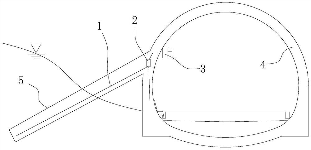
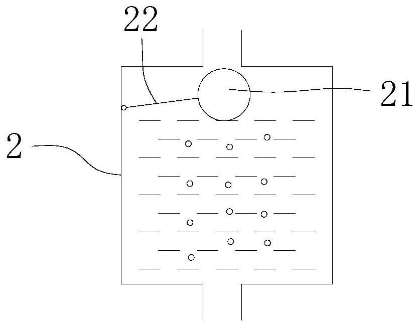
[0031] like figure 1 , figure 2 As shown, the drainage system of the tunnel operation period of the embodiment of the present invention includes a siphon pipe 1; it also includes an air collection box 2 and a wind power mechanism 3; the bottom of the air collection box 2 communicates with the highest point of the siphon pipe 1 through a connecting pipe;

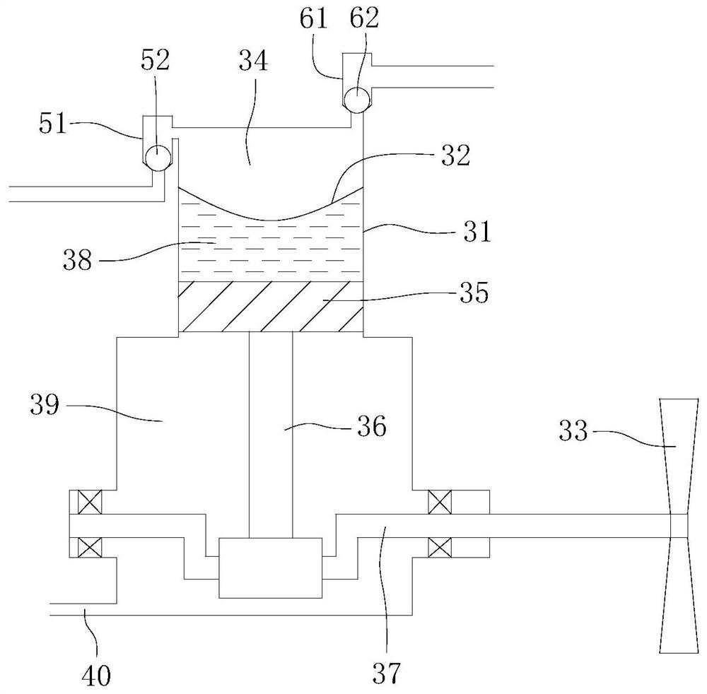
[0032] The wind power mechanism 3 includes an exhaust box 31, a diaphragm 32, a fan blade 33, a first one-way communication mechanism and a second one-way communication mechanism; the diaphragm 32 is arranged in the exhaust box 31, and the edge of the diaphragm 32 It is sealingly connected with the inner wall of the exhaust box 31, and div...


PUM


Abstract

The invention relates to the technical field of tunnel drainage, and provides a tunnel drainage system during operation, including a siphon pipe, an air collection box and a wind power mechanism; the bottom of the air collection box communicates with the highest point of the siphon pipe through a connecting pipe; the wind power mechanism It includes an exhaust box, a diaphragm, fan blades, a first one-way communication mechanism and a second one-way communication mechanism. A drainage method is provided during the operation period of the tunnel. The water in the surrounding rock of the tunnel is drained into the drainage ditch in the tunnel through the siphon pipe. When the train enters the tunnel, the piston wind generated by the train blows to the fan blades and drives the fan blades to rotate. The leaf drives the diaphragm to agitate back and forth through the transmission mechanism, and then discharges the air in the siphon. The drainage system and drainage method during the tunnel operation period of the embodiment of the present invention collect the air accumulated at the top of the siphon through the air collection box, and discharge the air in the air collection box through the wind power mechanism, thereby avoiding the failure of the vacuum degree at the top of the siphon and ensuring Siphon drainage works normally for a long time.

Description

technical field [0001] The invention relates to the technical field of tunnel drainage, in particular to a drainage system and a drainage method during tunnel operation. Background technique [0002] During the operation of the tunnel, water leakage in the tunnel not only affects the operation of the tunnel, but also destroys the structure of the tunnel and causes harm to the tunnel. Therefore, in order to solve the problem of tunnel water leakage, the water collection well is usually drilled obliquely downward in the surrounding rock of the tunnel at present, the water inlet end of the siphon is inserted into the bottom of the water collection well, and the water outlet of the siphon is placed in the drainage ditch in the tunnel. The water at the highest point in the tunnel flows to the outlet of the siphon under the action of gravity, and creates negative pressure at the top of the siphon, causing the water at the inlet of the siphon to be sucked into the pipe and flow to ...

Claims


Application Information

Patent Timeline
Patent Type & Authority Patents(China)
IPC IPC(8): E21F16/02F04F10/00
CPCE21F16/02F04F10/00
Inventor 周浩文付弦田和平任光辉
Owner CHINA 19TH METALLURGICAL CORP
Why Eureka
Try Eureka