
Semi-automatic loading and unloading bridge with route planning algorithm and control method

A path planning, loading and unloading bridge technology, applied in the field of control, can solve the problems of difficult loading and unloading of compartments, hidden compartments of ships, etc.

Active Publication Date: 2020-07-07
SHANGHAI MEISHAN IRON & STEEL CO LTD
View PDF9 Cites 7 Cited by
  • Summary
  • Abstract
  • Description
  • Claims
  • Application Information

AI Technical Summary

Problems solved by technology

[0003] The present invention is aimed at the problems existing in the prior art, and provides a semi-automatic loading and unloading bridge with a path planning algorithm. This technical solution improves operating efficiency, reduces operating personnel, and solves the problem of difficult loading and unloading of hidden cabins and compartments of ships.

Method used

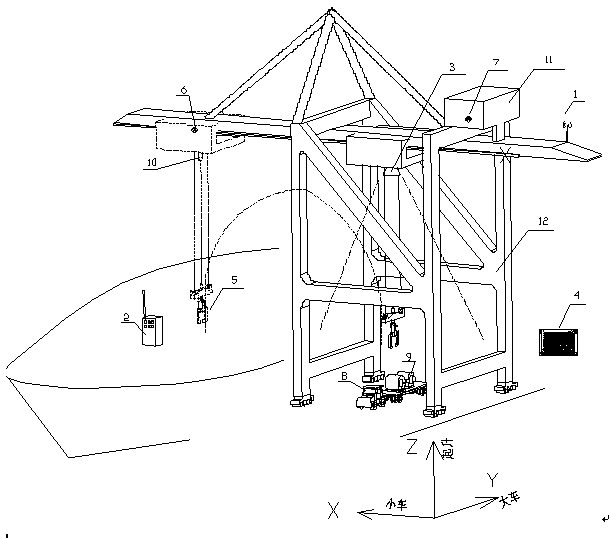
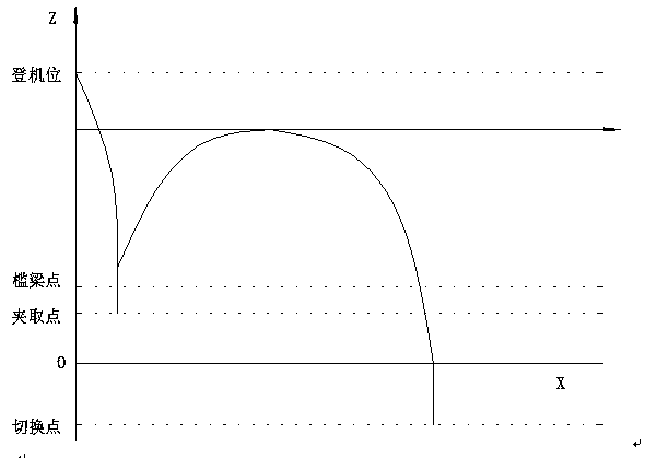
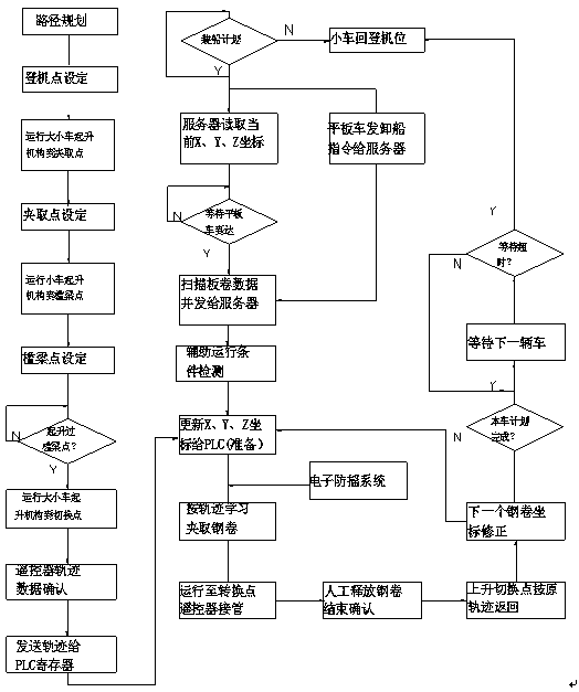

Image

  • Semi-automatic loading and unloading bridge with route planning algorithm and control method
  • Semi-automatic loading and unloading bridge with route planning algorithm and control method
  • Semi-automatic loading and unloading bridge with route planning algorithm and control method

Examples


Embodiment 1

[0031] Embodiment 1: see Figure 1-Figure 3 , a semi-automatic loading and unloading bridge with a path planning algorithm, which includes an outdoor UWB ultra-wideband cart wireless positioning device 1 for measuring the Y-axis coordinates of the cart defined in the system software; a position encoder installed on the motor shaft of the cart 6. It is used to measure the X coordinate of the car from the boarding position defined in the system software, and a set of laser ranging encoder is used as the position correction when the wheel slips; the encoder installed on the wire rope drum of the hoisting mechanism 7. It is used to measure the Z-axis coordinate of the lifting hook head starting from the ground. The loading and unloading bridge includes a support frame 12, a remote control device 2, an on-shore laser radar visual recognition device 3, an electronic anti-sway device 10, a ground control server 4, and an on-board PLC motion control system. The shaking device 10 is a...

Embodiment 2

[0032] Example 2: see Figure 1-Figure 3 , a semi-automatic loading and unloading bridge control method with path planning algorithm, the method comprises the following steps:

[0033] ①Path planning curve "boarding point" setting, A, cart initial position setting: the production operator sends the coordinates measured by the wireless positioning device to the ground control server in the transportation information system according to the position where the ship stops, and then the ground control The server sends it to the PLC motion control system on the machine to drive the cart to the designated position. B. The initial position setting of the trolley: the cab is parked at the position of the boarding platform, and there is a stop limit and position encoder detection of the trolley at this position. C. Lifting initial position setting: The lifting mechanism is at the upper stop limit position, which is detected by the lifting position encoder at the same time. The point whe...


PUM


Abstract

The invention relates to a semi-automatic loading and unloading bridge with a route planning algorithm. The loading and unloading bridge comprises a supporting frame, a remote control unit device, a shore laser radar visual recognition device, an electronic anti-swing device, a cart wireless locating device, a ground control server and an onboard PLC motion control system. The cart wireless locating device and the electronic anti-swing device are arranged on the supporting frame. The shore laser radar visual recognition device is arranged below the supporting frame. The loading and unloading bridge further comprises electric clamp forceps, a trolley position encoder and a lifting height encoder. The electric clamp forceps are arranged below a balance beam lifting hook. The trolley positionencoder and the lifting height encoder are arranged above the supporting frame. By means of the scheme, the semi-automatic loading and unloading bridge has the functions of route memorizing, automatic recognition to car types and plate coil coordinates and automatic plate coil clamping.

Description

technical field [0001] The invention relates to a loading and unloading bridge, in particular to a semi-automatic loading and unloading bridge with a path planning algorithm, which belongs to the technical field of control. Background technique [0002] Most of the freight ships at the wharf of Meishan Iron and Steel Co., Ltd. have compartments and hidden compartments in the middle. Loading efficiency and safety, two or one cableman will command the driver of the loading and unloading bridge to roll the cargo into the hidden cabin. The driver cannot see the cargo. He operates the loading and unloading bridge according to the command gesture, and then uses the inertia of the crane trolley to move the board. The volume rolled into the hidden cabin. The loading and unloading of steel coils at domestic ports are all manually loaded and unloaded, with low labor efficiency and no guarantee of safety. Therefore, it is necessary to develop a semi-automatic loading and unloading br...

Claims


Application Information

Patent Timeline
IPC IPC(8): B66C13/06B66C13/40B66C13/48B66C13/16B66C15/00
CPCB66C13/063B66C13/40B66C13/48B66C13/16B66C15/00
Inventor 王林詹红
Owner SHANGHAI MEISHAN IRON & STEEL CO LTD
Learn More