A steel ball screening machine with automatic material receiving function
An automatic material receiving and screening machine technology, applied in the field of wear-resistant steel ball production, can solve the problems of poor flexibility, inconvenient disassembly and replacement of the screening bucket, and poor adaptation of the sorting work, achieving high flexibility and simple operation convenient effect
- Summary
- Abstract
- Description
- Claims
- Application Information
AI Technical Summary
Problems solved by technology
Method used
Image


Examples
Embodiment 1
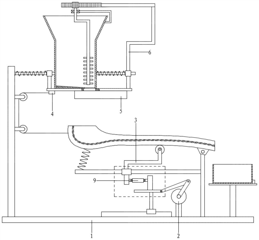
[0055] Referring to the accompanying drawings, a steel ball screening machine with an automatic material receiving function includes a frame assembly 1, a drive assembly 2, a material receiving assembly 3, a hole alignment assembly 4 and an adjustment assembly 5;
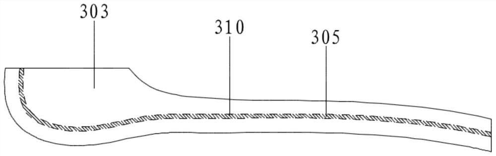
[0056] The frame assembly 1 includes a base 101, a column 102, a No. 1 pole 103 and a ball storage box 104. The left end of the base 101 is fixedly connected with a column 102, and the top of the column 102 is connected with a ball storage box 104 through the No. 1 pole 103 to the right. The inner bottom of the box 104 is processed with a slope 105 with a high left end and a low right end, and the low end has a ball outlet;
[0057] The driving assembly 2 is arranged on the base 101, the top of the driving assembly 2 is provided with a material receiving assembly 3, and the material receiving assembly 3 faces the ball outlet; the right side of the material receiving assembly 3 is provided with a material receiving bo...
Embodiment 2
[0059] Referring to the accompanying drawings, a steel ball screening machine with an automatic material receiving function includes a frame assembly 1, a drive assembly 2, a material receiving assembly 3, a hole alignment assembly 4 and an adjustment assembly 5;
[0060] The frame assembly 1 includes a base 101, a column 102, a No. 1 pole 103 and a ball storage box 104. The left end of the base 101 is fixedly connected with a column 102, and the top of the column 102 is connected with a ball storage box 104 through the No. 1 pole 103 to the right. The inner bottom of the box 104 is processed with a slope 105 with a high left end and a low right end, and the low end has a ball outlet;
[0061] The driving assembly 2 is arranged on the base 101, the top of the driving assembly 2 is provided with a material receiving assembly 3, and the material receiving assembly 3 faces the ball outlet; the right side of the material receiving assembly 3 is provided with a material receiving bo...
Embodiment 3
[0081] The difference from Example 2 is that
[0082] Also includes a disturbance assembly 6, the disturbance assembly 6 includes a second connecting rod 601, a third connecting rod 602, a moving rod 603 and a disturbing rod 604;
[0083] The bottom end of No. 2 connecting rod 601 is connected with No. 2 sliding sleeve 408 on the right side, and the top is connected with No. 3 connecting rod 602 to the left; the left end of No. 3 connecting rod 602 is fixedly connected with moving rod 603 downward; In the box 104, the lower segment is connected with a disturbance rod 604 at intervals.
[0084] Specifically, the wear-resistant steel balls are stacked in the ball storage box 104. In order to avoid the situation of balls not falling, it is necessary to disturb the wear-resistant steel balls so that the wear-resistant steel balls with small diameters fall to the bottom. When the device is in use, the moving plate 405 moves back and forth, and the No. 2 sliding sleeve 408 also mov...
PUM
 Abstract
Description
Claims
Application Information
 - Generate Ideas
- Intellectual Property
- Life Sciences
- Materials
- Tech Scout
- Unparalleled Data Quality
- Higher Quality Content
- 60% Fewer Hallucinations
Browse by: Latest US Patents, China's latest patents, Technical Efficacy Thesaurus, Application Domain, Technology Topic, Popular Technical Reports.
© 2025 PatSnap. All rights reserved.Legal|Privacy policy|Modern Slavery Act Transparency Statement|Sitemap|About US| Contact US: help@patsnap.com