
Wearable electrocardiogram real-time monitoring equipment

A real-time monitoring and electrocardiogram technology, applied in the field of medical devices, can solve the problems of no wearable function, no real-time patients, and inconvenient monitoring.

Inactive Publication Date: 2020-07-07
张玉强
View PDF10 Cites 1 Cited by
  • Summary
  • Abstract
  • Description
  • Claims
  • Application Information

AI Technical Summary

Problems solved by technology

[0003] The existing application number is CN201721923191.4 discloses an ECG monitoring device. By setting the vibrator in the central area of ​​the electrode assembly, the thickness of the electrode assembly can be made thicker in the middle and thinner on both sides, and the thickness of the electrode assembly is from the middle to both sides. Gradually decrease, so that the whole electrode assembly can be smaller and thinner, and when the vibrator is located in the central area of ​​the circuit board, the vibration force of the vibrator will spread from the middle to the four sides when vibrating, and the vibration effect will be better. When the ECG monitoring component monitors When the obtained ECG information is abnormal, it sends a vibration signal to the vibrator, but this setting cannot monitor the patient in real time, nor can it send an alarm in time when the patient has an abnormal heartbeat. The monitoring effect is not good, and it does not have wearable functions. Not convenient enough to monitor

Method used


Image

  • Wearable electrocardiogram real-time monitoring equipment
  • Wearable electrocardiogram real-time monitoring equipment
  • Wearable electrocardiogram real-time monitoring equipment

Examples


Embodiment Construction

[0026] The following will clearly and completely describe the technical solutions in the embodiments of the present invention with reference to the accompanying drawings in the embodiments of the present invention. Obviously, the described embodiments are only some, not all, embodiments of the present invention. Based on the embodiments of the present invention, all other embodiments obtained by persons of ordinary skill in the art without making creative efforts belong to the protection scope of the present invention.

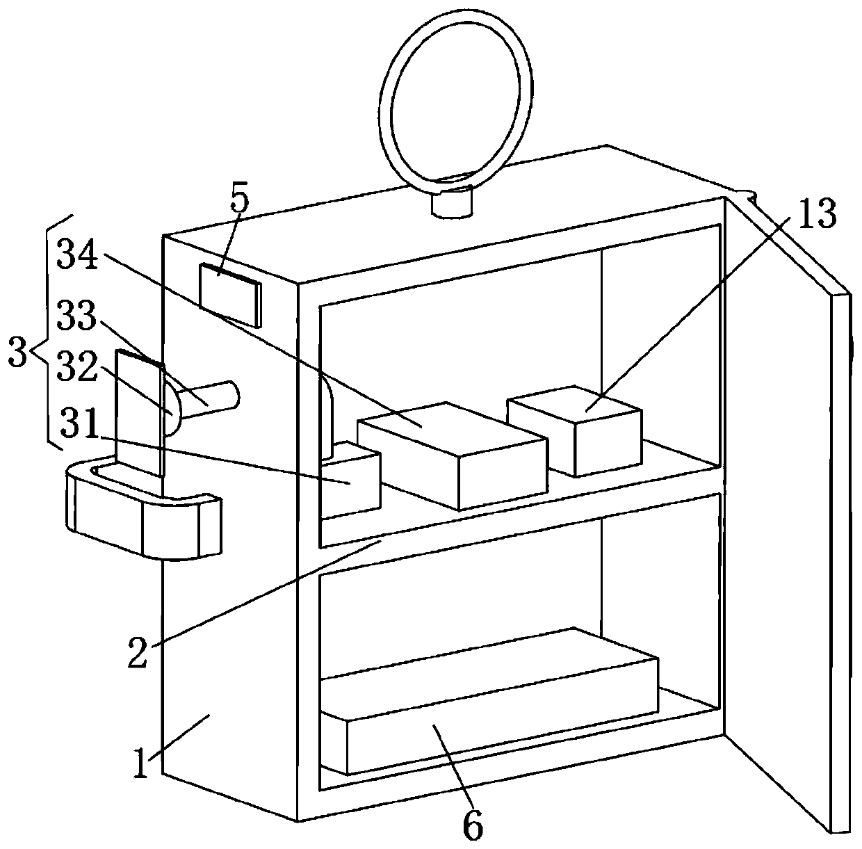
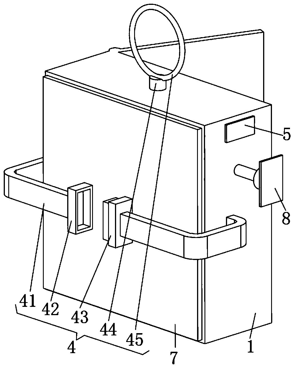
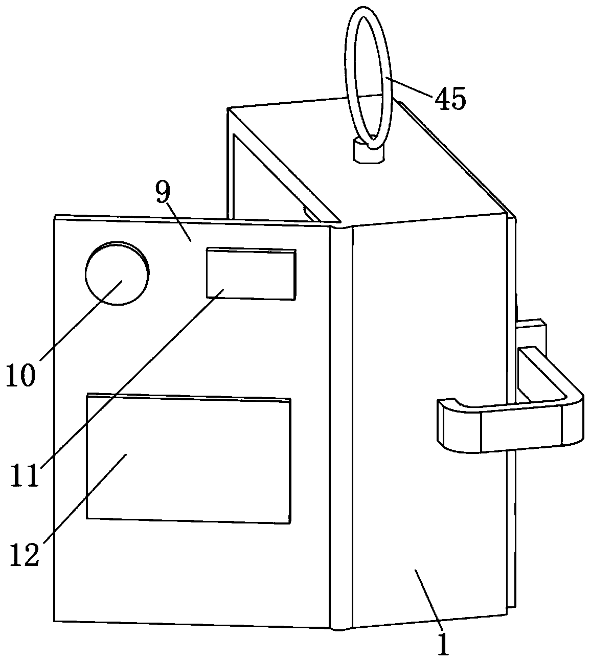
[0027] see Figure 1-3 , the present invention provides a technical solution: a wearable ECG real-time monitoring device, including a monitoring box 1, a monitoring unit 3 and a wearable unit 4;

[0028] Monitoring box 1: The monitoring box 1 is a cuboid, and a partition 2 is arranged inside the monitoring box 1;

[0029] Monitoring unit 3: The monitoring unit 3 includes a current amplifier 31, an electrode sheet 32, a connecting wire 33 and a signal transmit...


PUM


Abstract

The invention discloses wearable electrocardiogram real-time monitoring equipment. A monitoring box is a cuboid, wherein a partition plate is disposed within the monitoring box; a current amplifier and a signal transmitter are both disposed on the partition plate; the input end of the current amplifier is connected to one end of a connecting line, and the other end of the connecting line is electrically connected to the output end of an electrode sheet by passing through the monitoring box; the electrode sheet is a magnetic metal sheet; the number of elastic ropes is two, and the two elastic ropes are arranged on the left side and the right side of the monitoring box receptively; one ends of the two elastic ropes are fixedly connected with the monitoring box, and the other ends of the twoelastic ropes are provided with a clamping ring and a clamping block respectively; a connecting column is arranged on the upper surface of the monitoring box; the lower end of the connecting column isrotatably connected with the monitoring box; and the upper end of the connecting column is fixedly connected with a wearing ring, so that a patient can be monitored in real time, an alarm can be sentin time when the patient is abnormal in heartbeat, the monitoring effect is relatively good, the wearable function is achieved, and the monitoring is relatively convenient.

Description

technical field [0001] The invention relates to the technical field of medical devices, in particular to a wearable electrocardiogram real-time monitoring device. Background technique [0002] The electrocardiogram is used to capture the reflection of the heart over a period of time. It is collected by external electrodes connected to the skin and converted into electrical signals. Each cell membrane formed on the outside of the heart has an associated charge, and the associated charge is depolarized during each heartbeat. It exists in the skin in the form of tiny electrical signals, so it can be detected and magnified by the electrocardiogram; [0003] The existing application number is CN201721923191.4 discloses an ECG monitoring device. By setting the vibrator in the central area of ​​the electrode assembly, the thickness of the electrode assembly can be made thicker in the middle and thinner on both sides, and the thickness of the electrode assembly is from the middle to...

Claims


Application Information

Patent Timeline
Patent Type & Authority Applications(China)
IPC IPC(8): A61B5/0402A61B5/0428A61B5/308
CPCA61B5/746A61B5/6802A61B5/7405A61B5/742A61B5/7225A61B5/30A61B5/318
Inventor 张玉强陈冉
Owner 张玉强
Learn More